
You are using an out of date browser. It may not display this or other websites correctly.
You should upgrade or use an alternative browser.
You should upgrade or use an alternative browser.
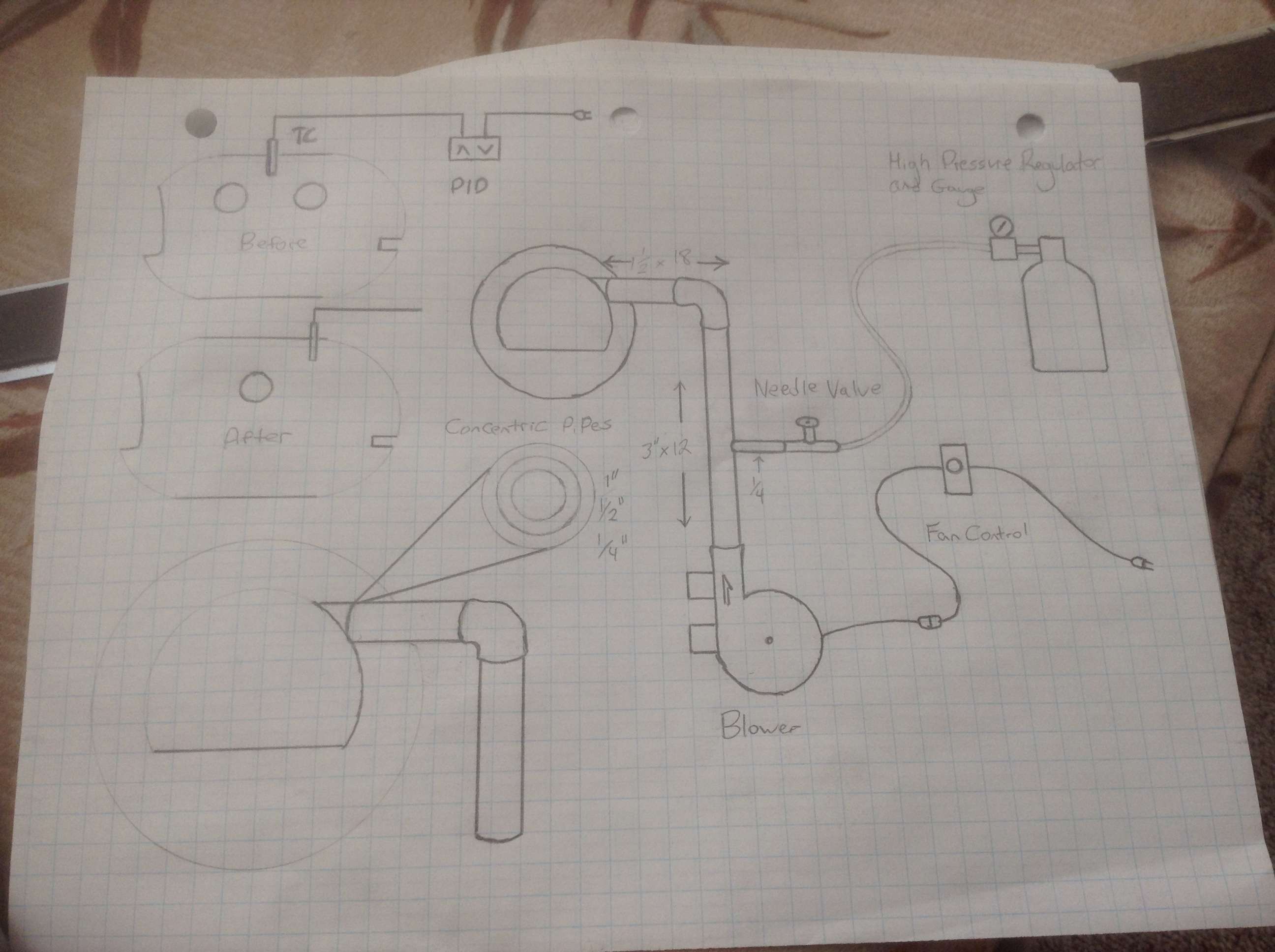
Diagram for Ed Caffrey
- Thread starter Forgedog
- Start date
Bruce McLeish
Well-Known Member
You don't use the pid in the after pic?
Bruce McLeish
Well-Known Member
ThanksPID will be there yes... Moving to the back of the forge body.
The diagrams just not to scale and I left that detail out.
I see in your drawing you're planning the concentric rings Ed talked about in this post:
https://knifedogs.com/threads/another-burner-problem-with-pics.50416/ where he wrote
When using a 1.5" burner tube I can see the advantage of those concentric rings, they'll effectively reduce the flow to match a 1" or 1-1/4" burner tube and provide better air/gas mixing. How do you plan to build those rings (attach each size pipe together and to 1.5" burner tube)? What thickness of pipe do you plan for the rings? Since I read this in Ed's post I've been thinking about this idea and working out details.
https://knifedogs.com/threads/another-burner-problem-with-pics.50416/ where he wrote
"for the last 3" I have a 1" inside the 1 1/2", a 3" piece of 1/2" inside that, and finally a 3" piece of 1/4" inside that. Some folks call it a "flame holder", or whatever, for me it's most important function is to quiet the burner. Without, it literally sounds like a jet engine in the shop.....with it, it's more a gentle roar, and is tolerable, and with ear plugs in barely noticeable."
When using a 1.5" burner tube I can see the advantage of those concentric rings, they'll effectively reduce the flow to match a 1" or 1-1/4" burner tube and provide better air/gas mixing. How do you plan to build those rings (attach each size pipe together and to 1.5" burner tube)? What thickness of pipe do you plan for the rings? Since I read this in Ed's post I've been thinking about this idea and working out details.
I see in your drawing you're planning the concentric rings Ed talked about in this post:
https://knifedogs.com/threads/another-burner-problem-with-pics.50416/ where he wrote
When using a 1.5" burner tube I can see the advantage of those concentric rings, they'll effectively reduce the flow to match a 1" or 1-1/4" burner tube and provide better air/gas mixing. How do you plan to build those rings (attach each size pipe together and to 1.5" burner tube)? What thickness of pipe do you plan for the rings? Since I read this in Ed's post I've been thinking about this idea and working out details.
I was thinking about this as well. I think maybe I'd try slotting all the tubes down the middle for about an inch deep and an 1/8" wide and then using some 1"x1/8" flat bar in the slots start welding from the littlest tube outwards. TIG would be nice to minimize the weld size. Maybe something to experiment with on my forge when I get it running.
EdCaffreyMS
"The Montana Bladesmith"
OK..... finally got to look the drawing over. Here's my input:
1. 3" pipe MIGHT work between the blower and elbow.....but it might be too much....I'm not sure. I suppose it's better to have to "dial down" the blower, then to not have enough velocity.
2. Place the needle valve as close to the blower as the pipe will allow. The further that fuel input is from the ignition point, the better the fuel/air mix will be.
Everything else looks good to me! If you use a pyrometer/thermocouple.... make sure you place it near the rear of the forge, ON THE SAME SIDE AS THE BURNER. That will be the coldest area of the forge, and I prefer to know that, more so than knowing where the hottest area is.")
1. 3" pipe MIGHT work between the blower and elbow.....but it might be too much....I'm not sure. I suppose it's better to have to "dial down" the blower, then to not have enough velocity.
2. Place the needle valve as close to the blower as the pipe will allow. The further that fuel input is from the ignition point, the better the fuel/air mix will be.
Everything else looks good to me! If you use a pyrometer/thermocouple.... make sure you place it near the rear of the forge, ON THE SAME SIDE AS THE BURNER. That will be the coldest area of the forge, and I prefer to know that, more so than knowing where the hottest area is.
Gene Kimmi
KNIFE MAKER
Not sure if it's needed, but I put a ball valve in the gas line right before the needle valve so I can shut the gas off fast if I need to. I've got the burner unit built, but still need to build the forge, so I haven't used it yet to see if it's needed.
Thanks Ed! I think you have answered all my questions and more now. Tomorrow ill pick up the remaining odds and ends and get this going!
To the others that replied. I also like that concentric pipe idea. They way it was mentioned to me is to use 1/4" square, keystock im thinking, placed between each of the pipes and tack welded at the ends.
Gene, do you mean a quick close to give you time to close needle valve?
To the others that replied. I also like that concentric pipe idea. They way it was mentioned to me is to use 1/4" square, keystock im thinking, placed between each of the pipes and tack welded at the ends.
Gene, do you mean a quick close to give you time to close needle valve?
Gene Kimmi
KNIFE MAKER
Yes, a 1/4 turn, ball valve.