J S Machine
Well-Known Member
I have decided to go ahead with this knife. This will be my second slipjoint. It will be very similar to my first slipjoint WIP, as some of the parts are actually left over from the batches I cut from that.
The story behind this knife is kind of interesting. I hope it raises some interest. Talking to my fire Asst. Chief about MDA the other night, we came up with this idea. Ever year, We collect money by standing in various locations holding a boot. I'm sure many of you have put money in one before..
He suggested that I make a knife, and we raffle off chances to win it. As of right now, we are talking about guaranteed 200 tickets at a cost of around $20 per ticket. If this is done and all the tickets sell, this will raise $4000 for MDA.
What I have decided to use for this knife are some materials I have had around for a while. As many of you know, I don't work very fast, or often for that matter. I had considered making myself another pocket knife to carry because the one I am currently carrying needs to be replaced, but this came up. I will be doing this for the next couple of weeks.
I have chosen a damascus blade from some damascus I got from a member here. He is from Pakistan; or the company is, and I got in on a buy one get one free deal he had going last year. I actually bought four bars of this stuff. Whether or not the stuff is any good was hotly debated and the thread was actually closed because of it, but I chose to pull the trigger. Fortunately, I got mine but I just haven't used it yet. Maybe no issues will arise with it.
The handle scales will be fossil mammoth tooth. Maybe not the best choice for scales, but let's see what we can do to make them work. The other parts will be a mix of 410SS and I think the spring is AEBL. my first blade and spring were AEBL and I have had no problems with it. Seems some are unsure about AEBL, I'm not sure why.
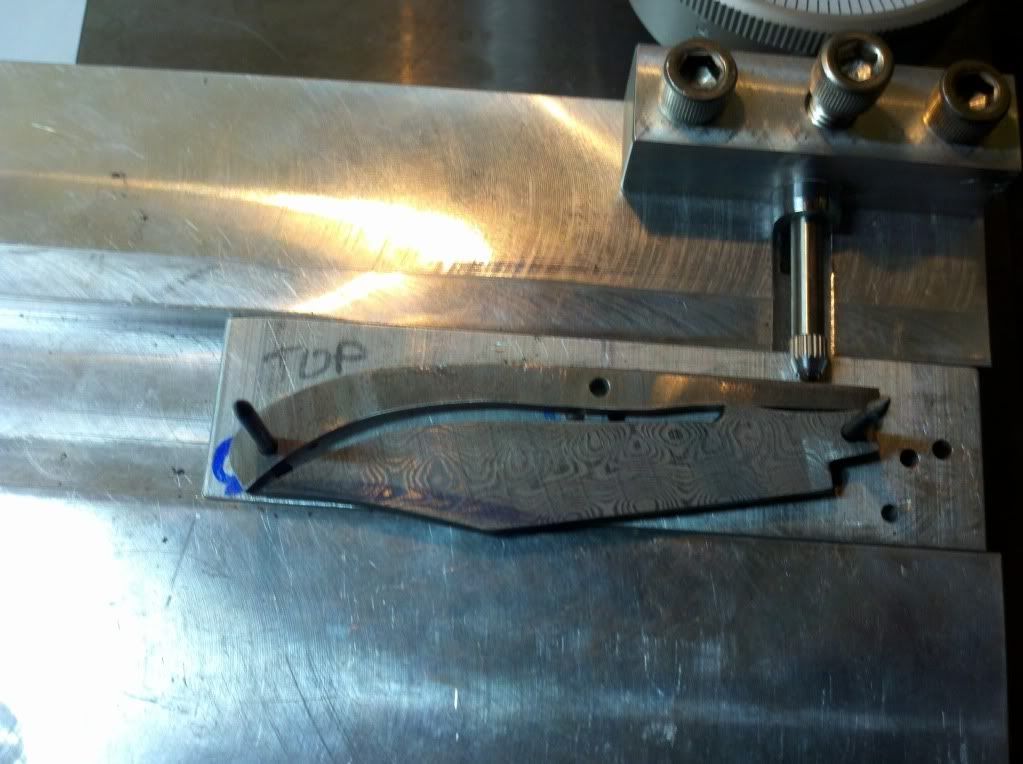
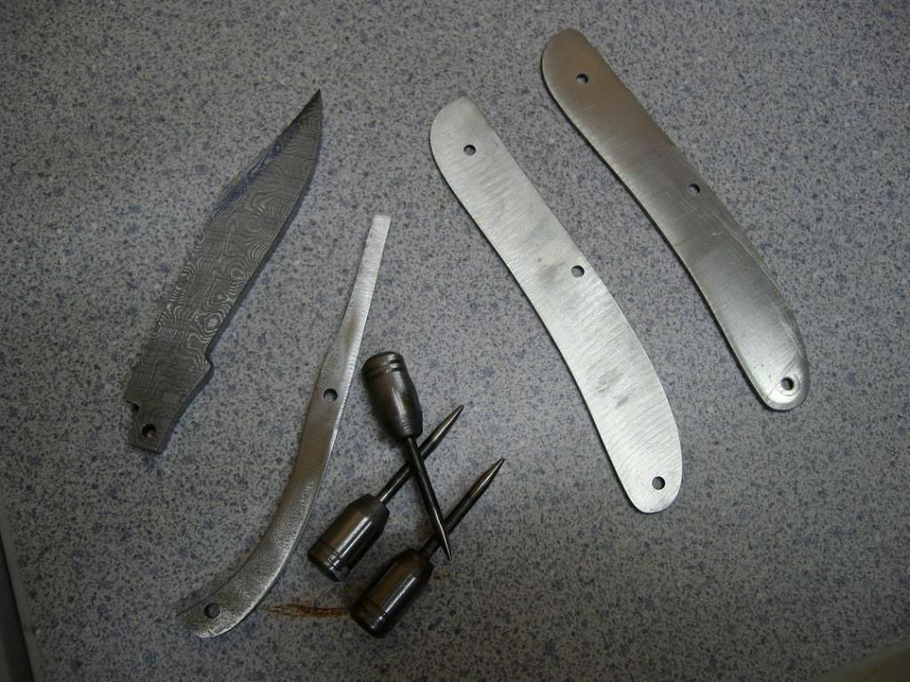
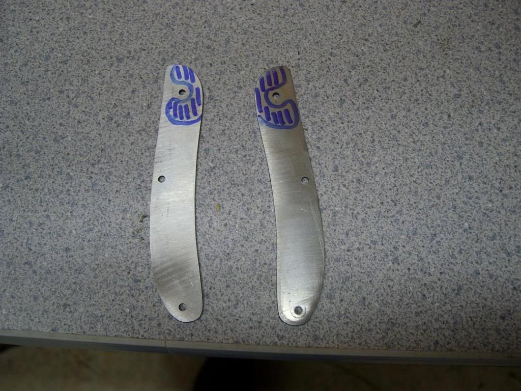
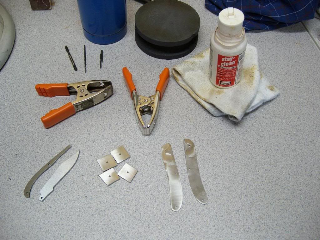
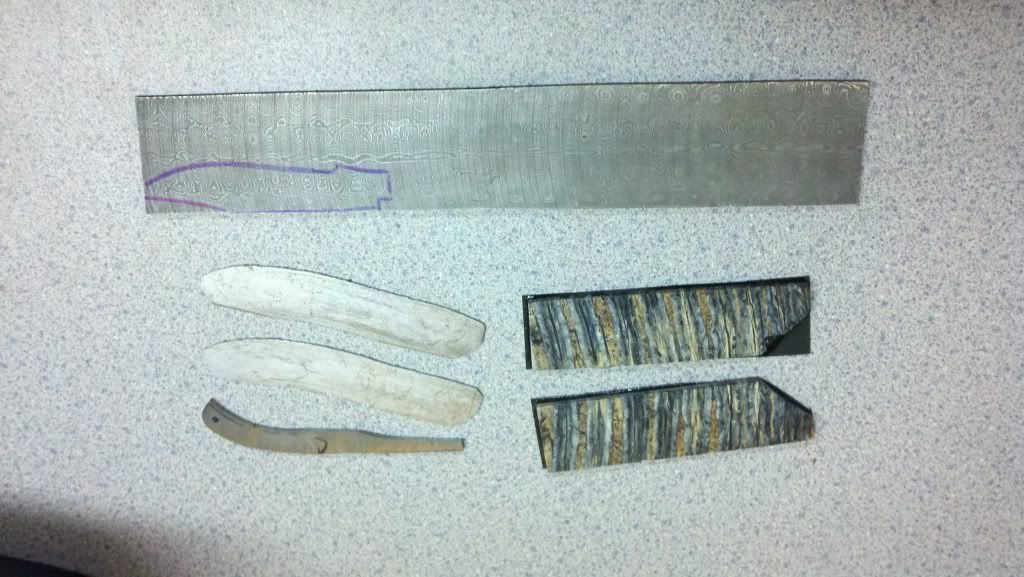
We start with some simple materials. Here we have the billet of damascus with the blade drawn out, the liners, and the scales. They are glued to Black fiber spacer material for support. The mammoth tooth came from Charles Turnage, and he actually recommends that you do that to stabilize it more-
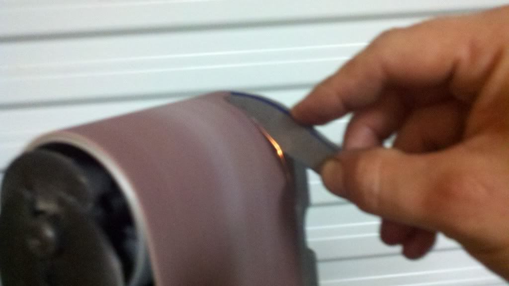
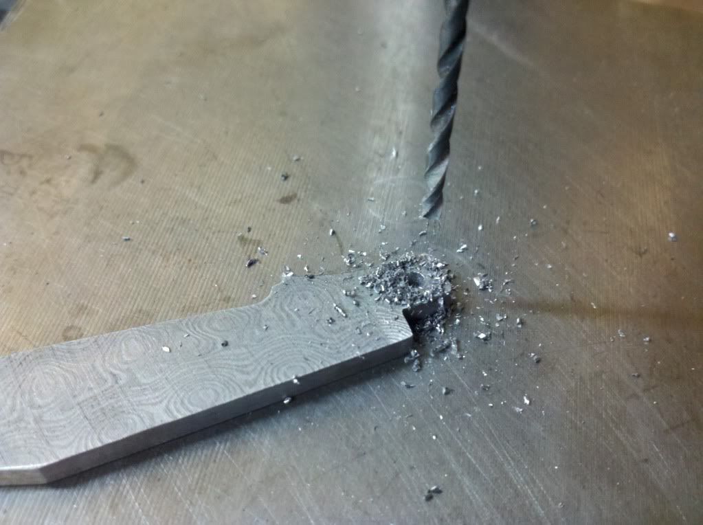
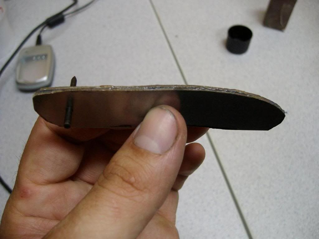
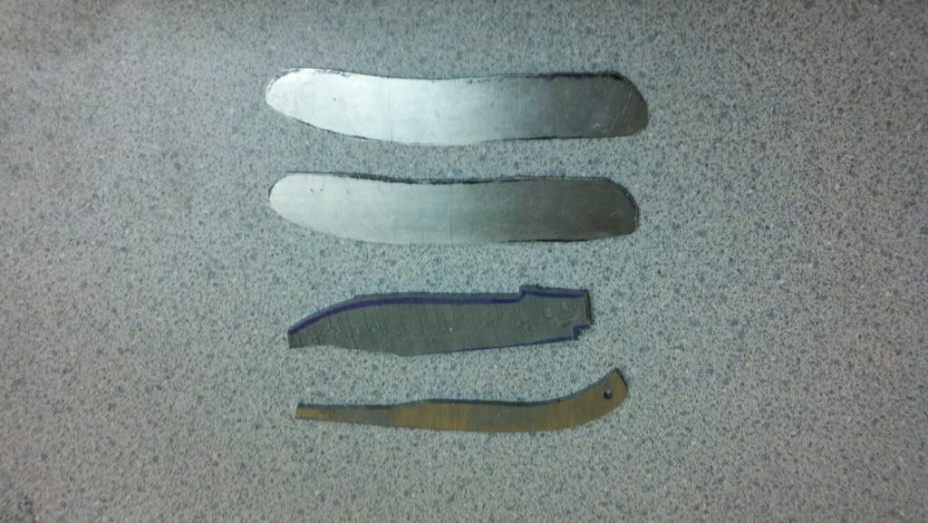
In this second picture I have cut the blade out with a portable band saw. My saw is set up where I can stand it up and use it like a vertical pedestal saw-
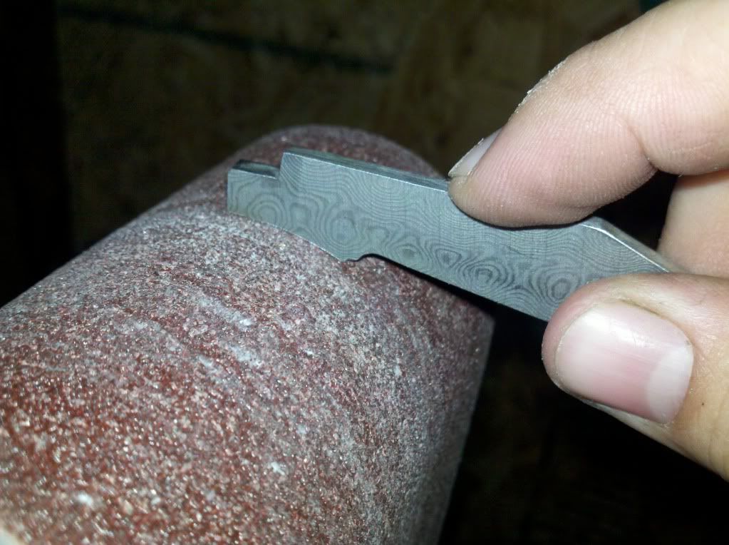
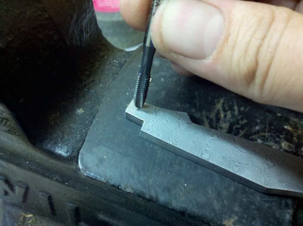
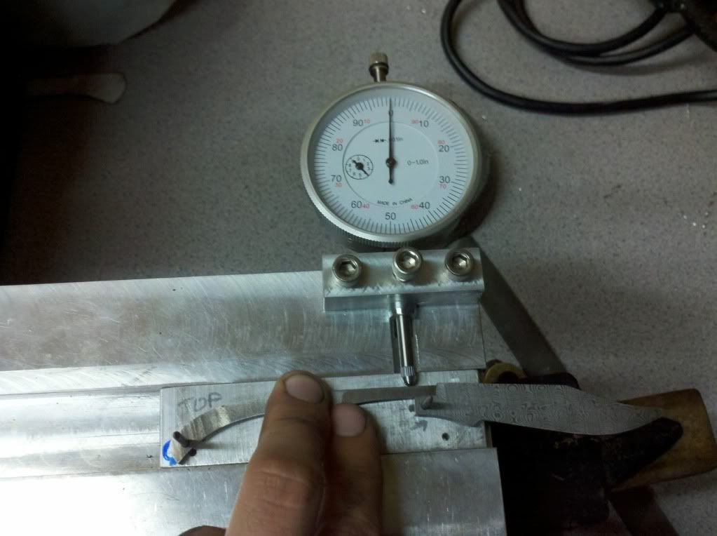
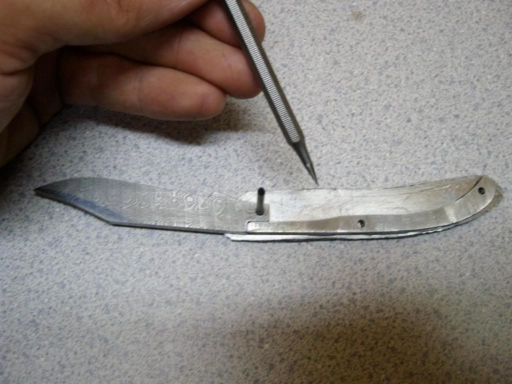
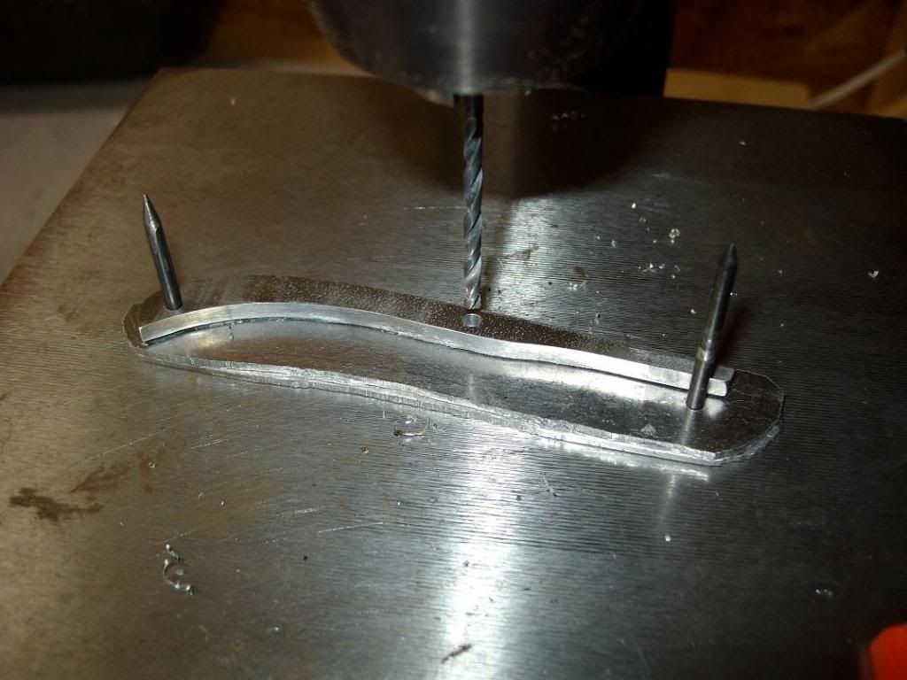
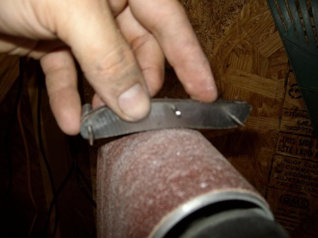
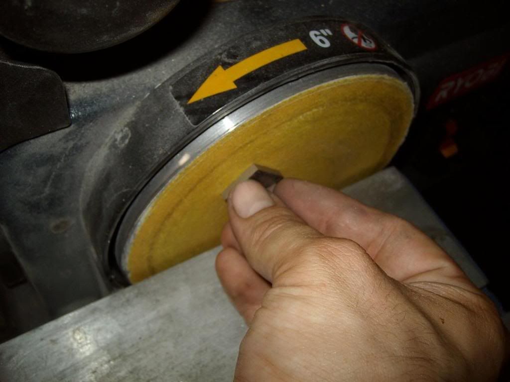
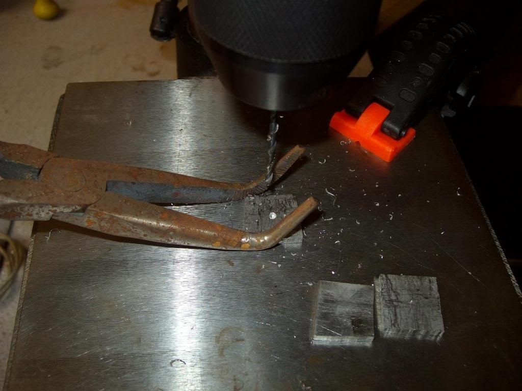
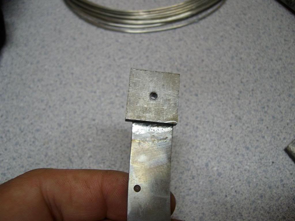
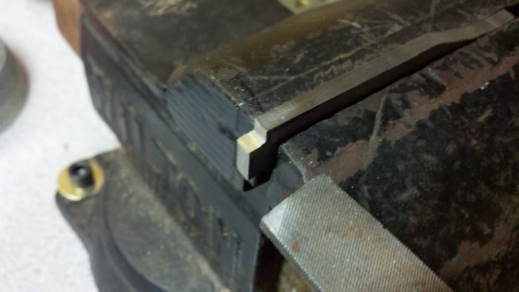
Here I am starting the notch in the back of the blade where the spring will rest. It is very critical that this stays square and straight, and the two need to match up perfectly when finished-
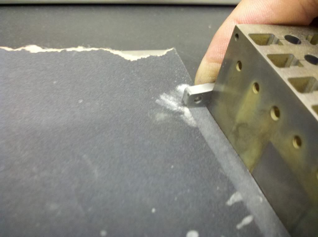
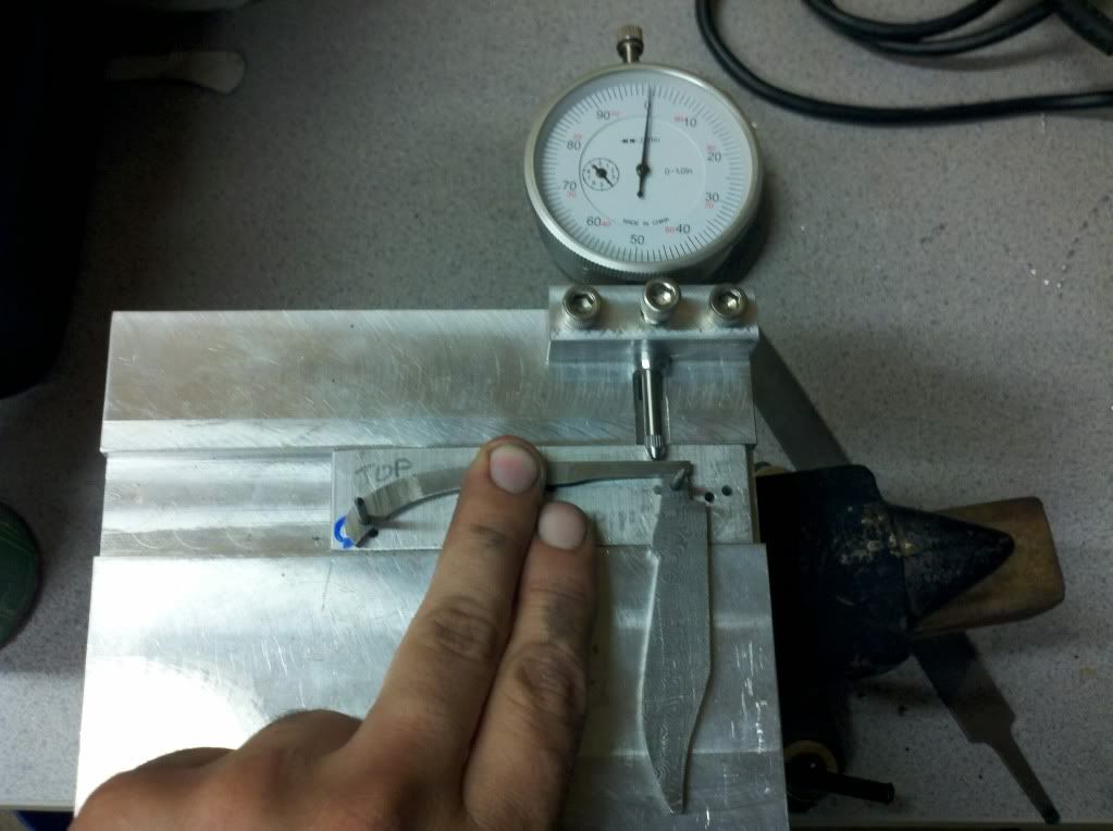
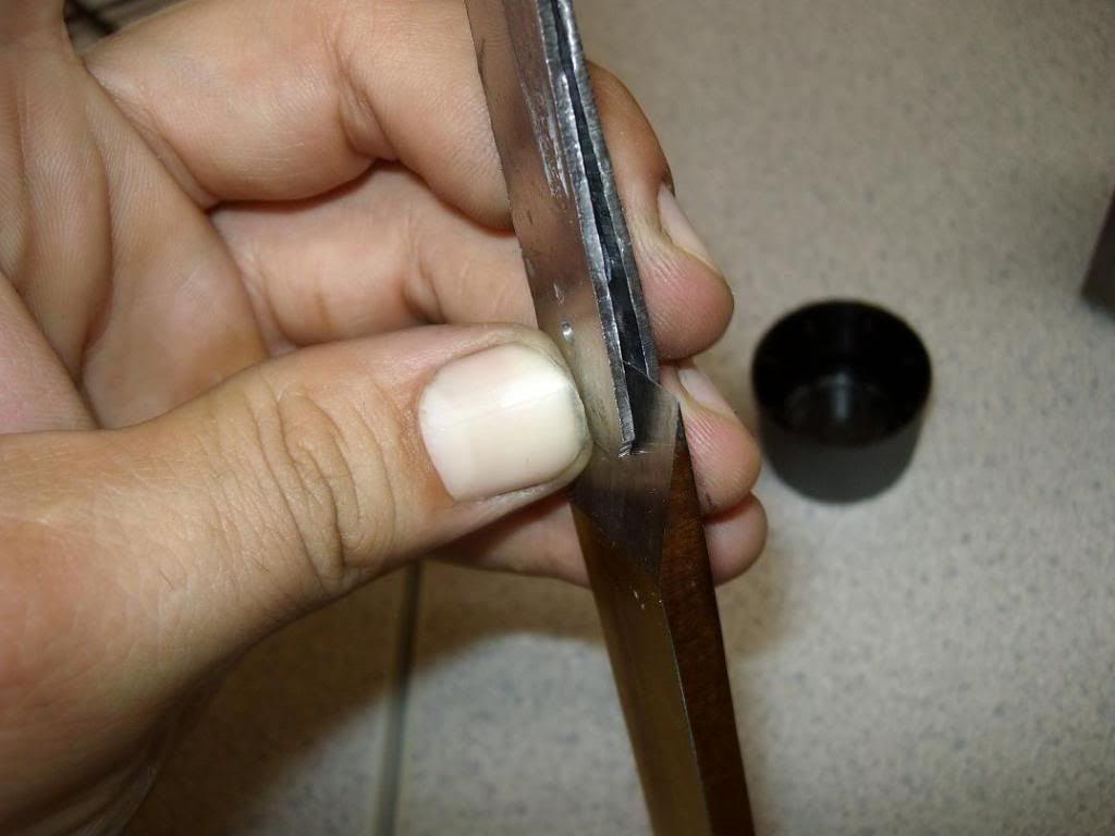
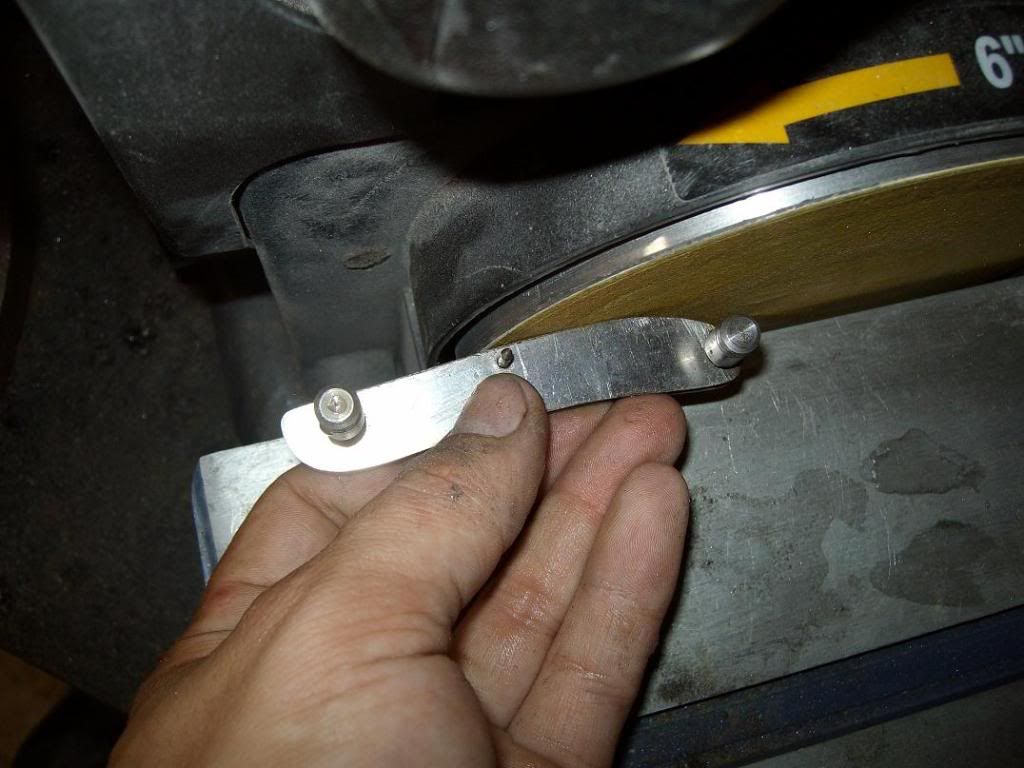
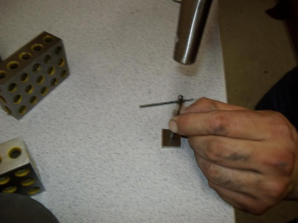
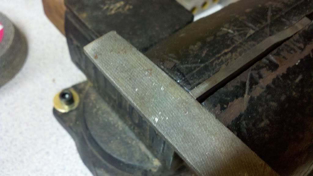
Making the cut with a file-
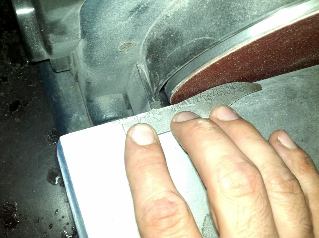
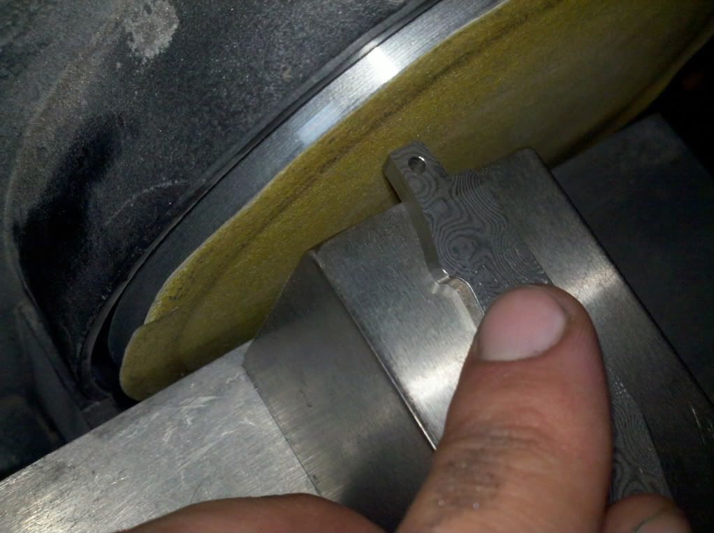
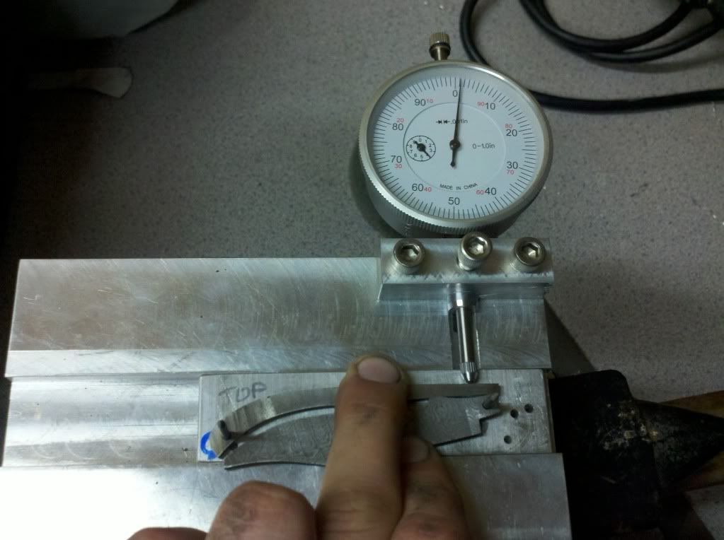
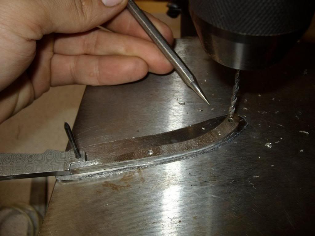
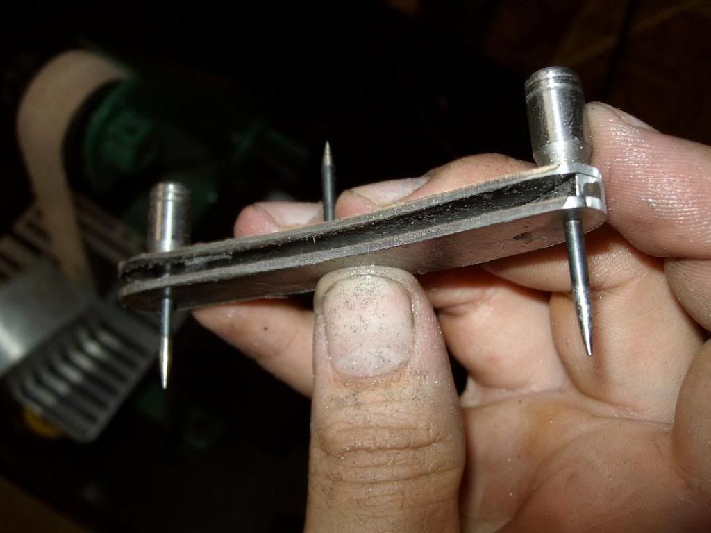
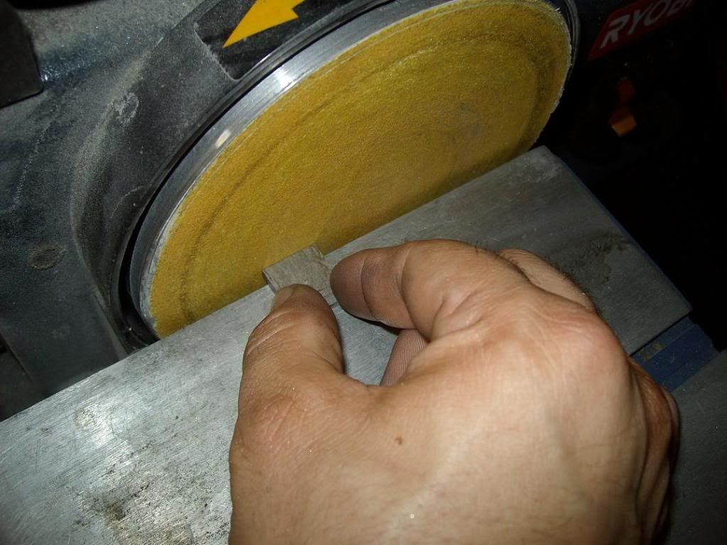
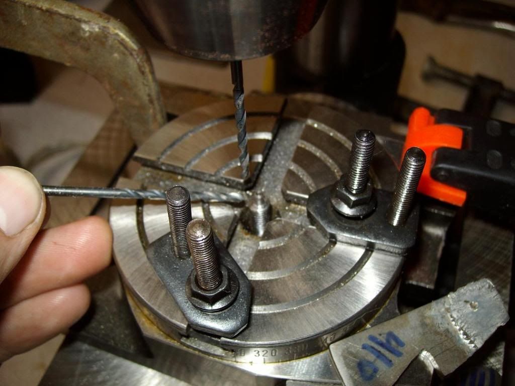
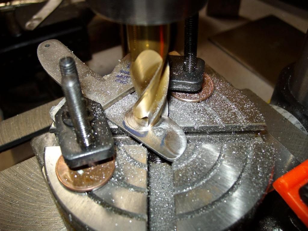
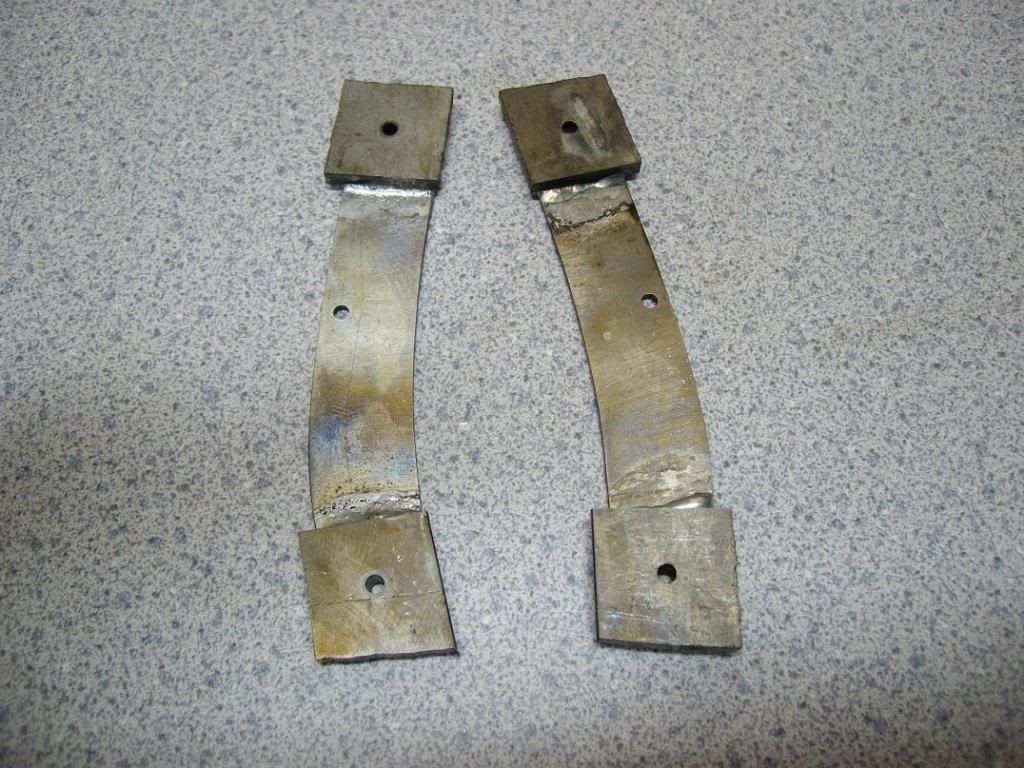
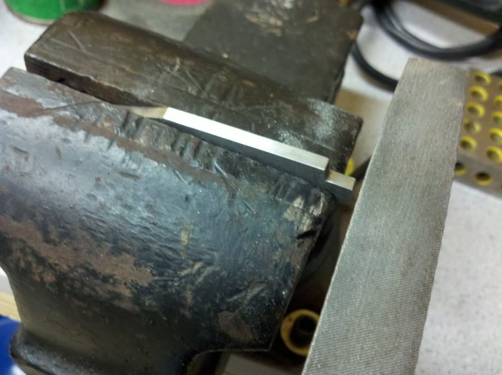
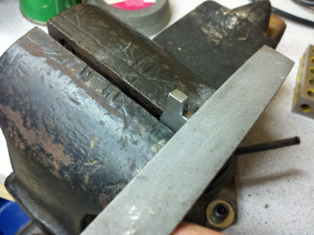
After realizing that I wasn't far enough in, I cut in about twice the depth. It is now the right depth for the blade and spring pair. Here we are cutting it at two different holds in the vise-
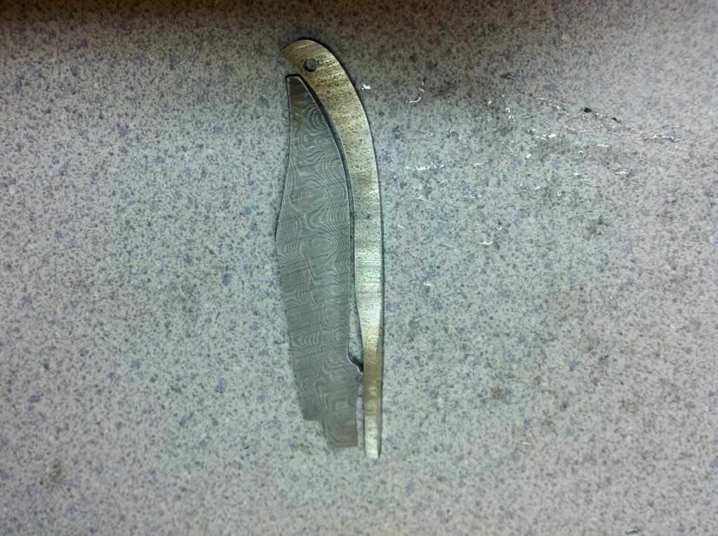
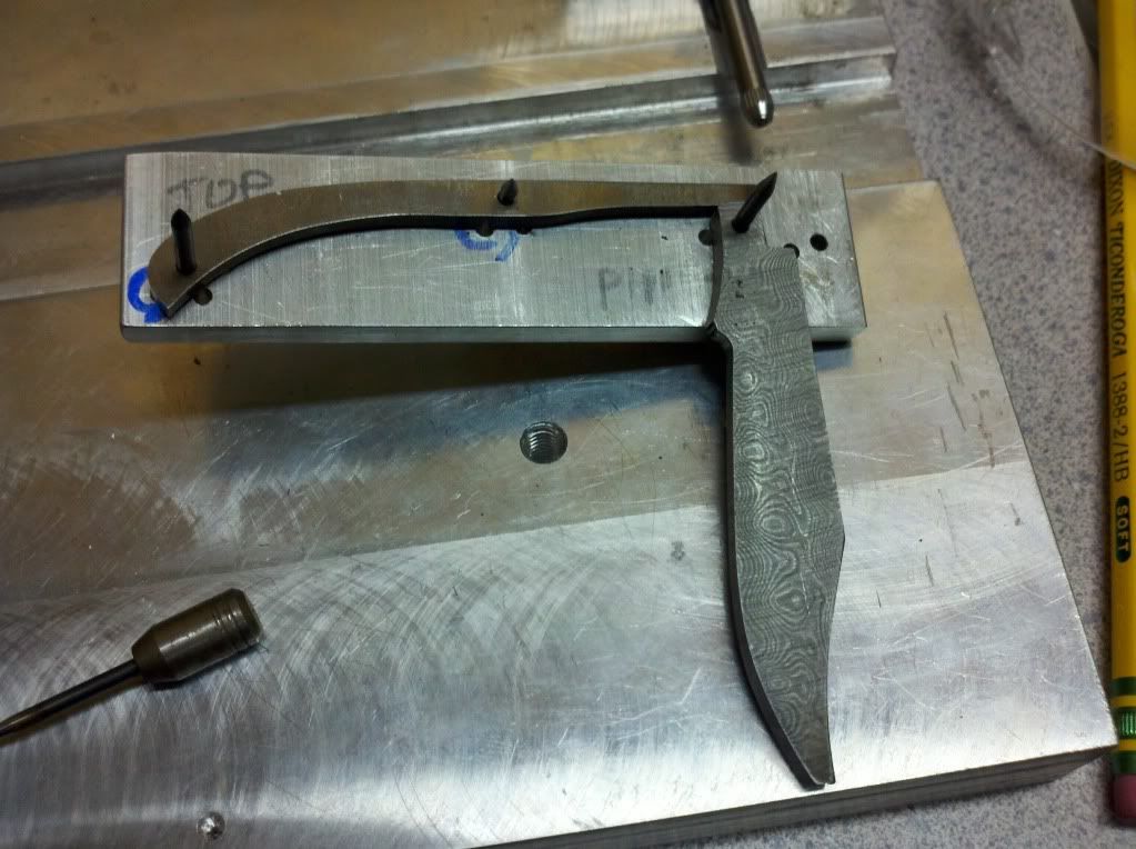
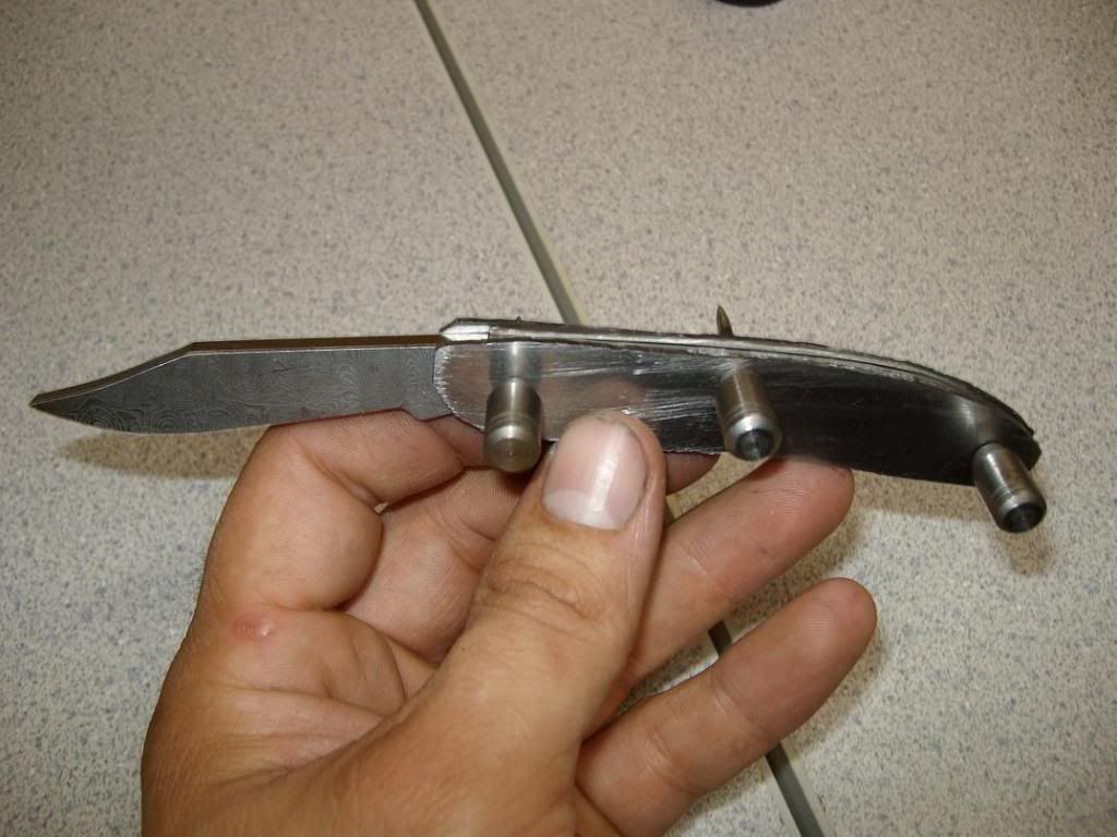
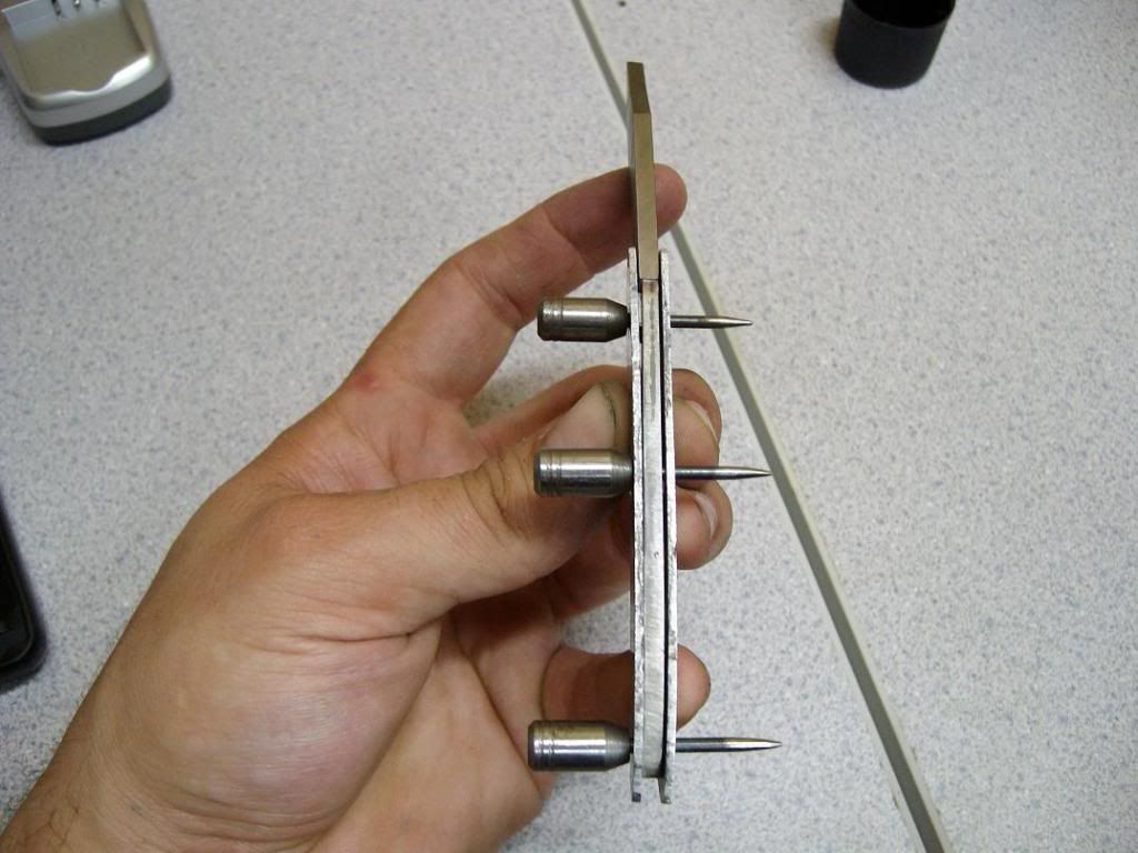
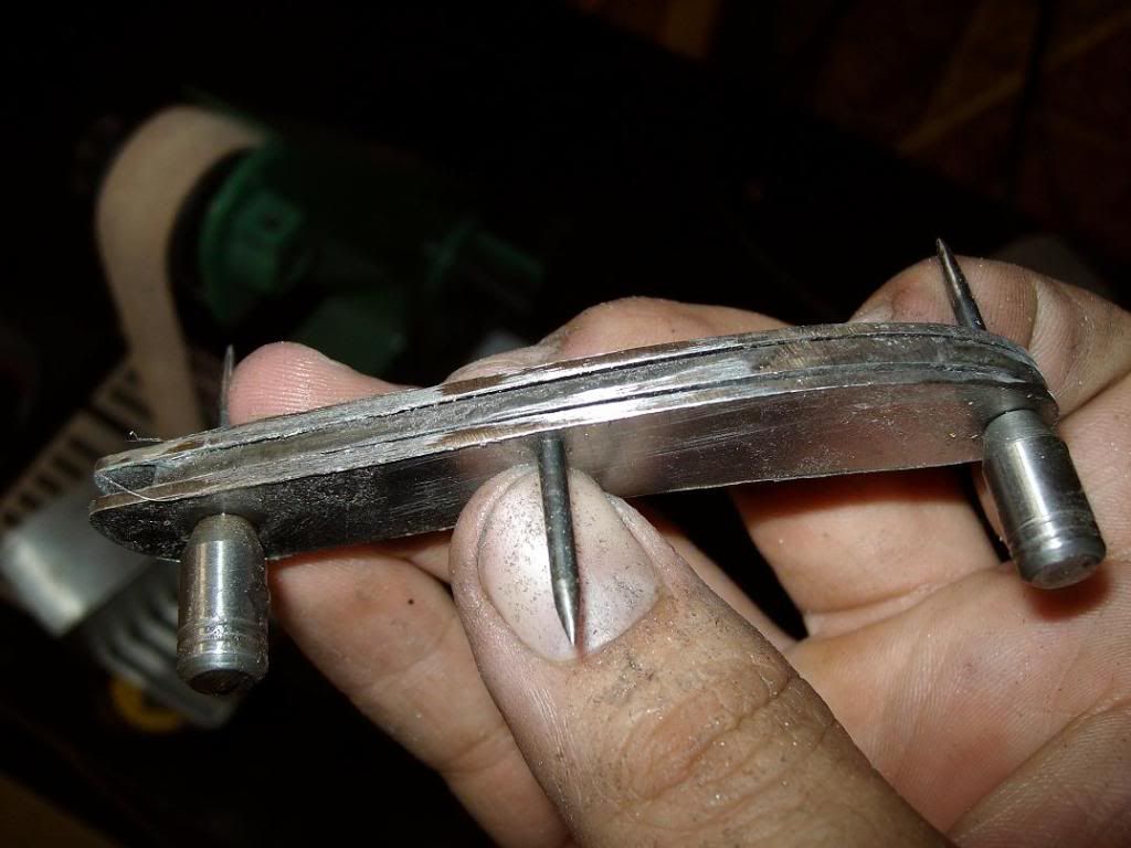
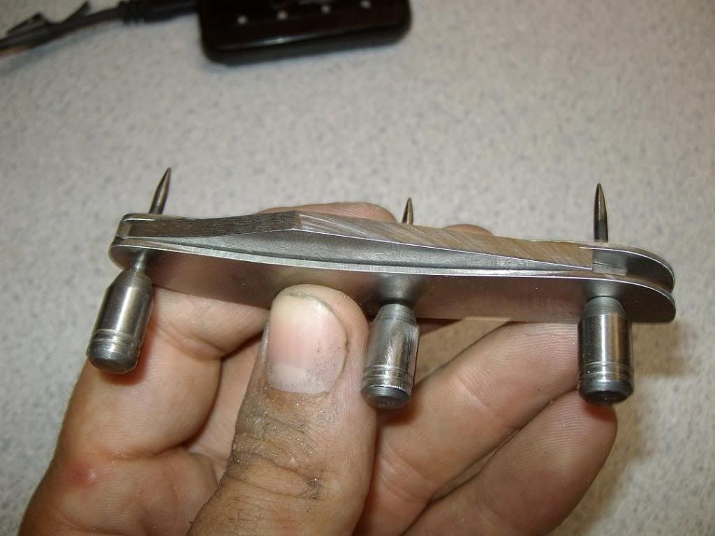
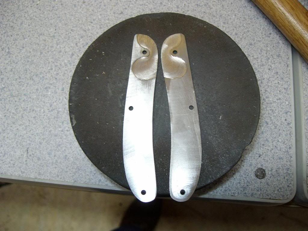
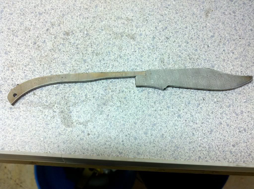
And here they are matched up. These still have to be touched up to fit perfect but this is close-
More to come, Stay tuned
The story behind this knife is kind of interesting. I hope it raises some interest. Talking to my fire Asst. Chief about MDA the other night, we came up with this idea. Ever year, We collect money by standing in various locations holding a boot. I'm sure many of you have put money in one before..
He suggested that I make a knife, and we raffle off chances to win it. As of right now, we are talking about guaranteed 200 tickets at a cost of around $20 per ticket. If this is done and all the tickets sell, this will raise $4000 for MDA.
What I have decided to use for this knife are some materials I have had around for a while. As many of you know, I don't work very fast, or often for that matter. I had considered making myself another pocket knife to carry because the one I am currently carrying needs to be replaced, but this came up. I will be doing this for the next couple of weeks.
I have chosen a damascus blade from some damascus I got from a member here. He is from Pakistan; or the company is, and I got in on a buy one get one free deal he had going last year. I actually bought four bars of this stuff. Whether or not the stuff is any good was hotly debated and the thread was actually closed because of it, but I chose to pull the trigger. Fortunately, I got mine but I just haven't used it yet. Maybe no issues will arise with it.
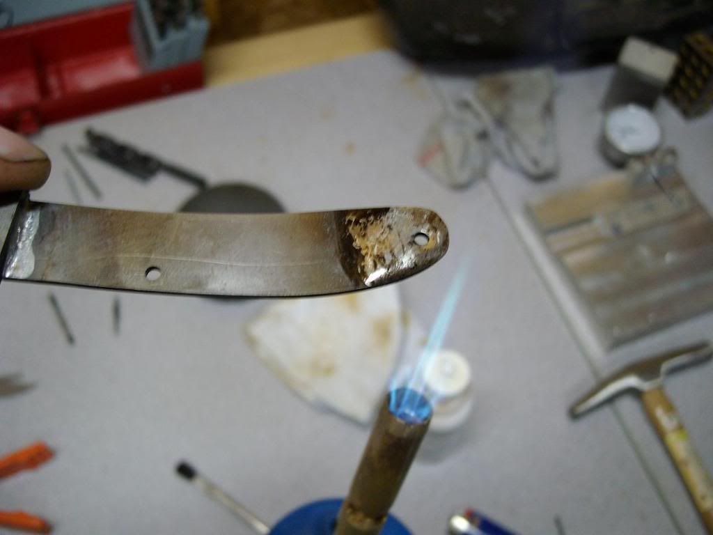
The handle scales will be fossil mammoth tooth. Maybe not the best choice for scales, but let's see what we can do to make them work. The other parts will be a mix of 410SS and I think the spring is AEBL. my first blade and spring were AEBL and I have had no problems with it. Seems some are unsure about AEBL, I'm not sure why.
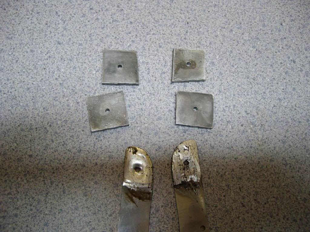
We start with some simple materials. Here we have the billet of damascus with the blade drawn out, the liners, and the scales. They are glued to Black fiber spacer material for support. The mammoth tooth came from Charles Turnage, and he actually recommends that you do that to stabilize it more-
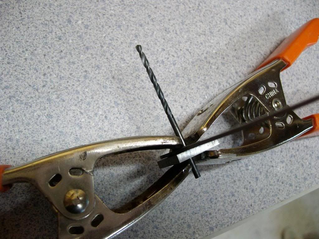
In this second picture I have cut the blade out with a portable band saw. My saw is set up where I can stand it up and use it like a vertical pedestal saw-
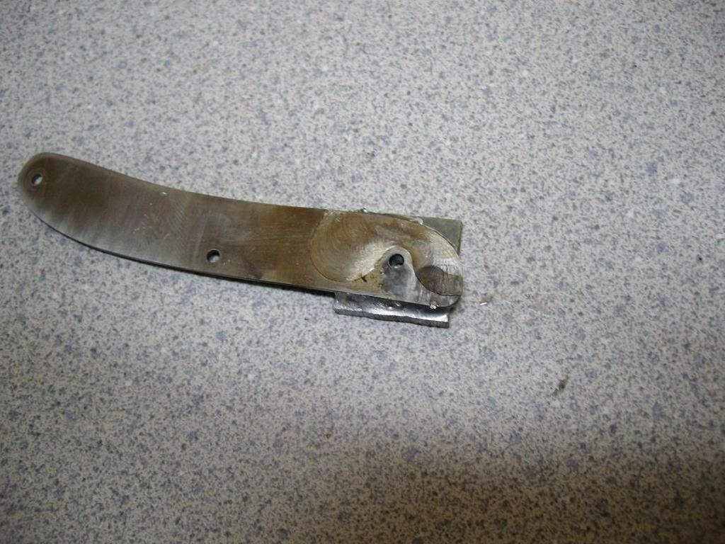
Here I am starting the notch in the back of the blade where the spring will rest. It is very critical that this stays square and straight, and the two need to match up perfectly when finished-
Making the cut with a file-
After realizing that I wasn't far enough in, I cut in about twice the depth. It is now the right depth for the blade and spring pair. Here we are cutting it at two different holds in the vise-
And here they are matched up. These still have to be touched up to fit perfect but this is close-
More to come, Stay tuned