Josh Dabney
Moderator
I wanna start right off the bat by sending out a big THANK YOU to Brian Fellhoelter for bringing this issue to light for me.
This thread is great reading for both KMG owners and those who are building their own grinder. Pay perticular attension to posts # 15 & 16 for a great explaination of the allignment issues at hand-
http://www.bladeforums.com/forums/showthread.php?t=831688&highlight=kmg+tweaks
This thread got me taking a closer look at my own grinder and quite obviously I had the same problems- Axles of the drive, tracking, and idler wheels NOT parallel and centerlines of wheels also misalligned.
I did quite a bit of looking at the grinder sizing up the situation and thinking about what the actual problems were and how to correct them and here's what I came up with-
The part of the puzzel that seemed the hardest to modify in any way was the driveshaft so squaring everything else off the driveshaft was my approach.
The wheels mounted to the tooling arms were in fact perpendiclar to the tooling arm itself so squaring the tooling arm (when tightened) with the driveshaft makes the idler wheel axles parallel to the driveshaft.
There are 8 bolts that go down through the tooling arm reciever that hold the entire top end of the machine together. There is some play in the holes for these bolts so if someone didn't want to permanently modify their machine they CAN loosen these bolts to use that "play" to change the allignment between the tooling arm and the driveshaft. On my grinder doing this gave me approximately 50% of what I needed to get to square so further modification was needed.
Because of that "play" in the bolt holes I figured I could mill out the holes for the front "leg" mounting bolts to make them slots instead of holes to allow a range of adjustment to get the tooling arm reciever squared with the driveshaft. At this point a complete tear down became needed to get any further so I unbolted the grinder from the bench and got to it.
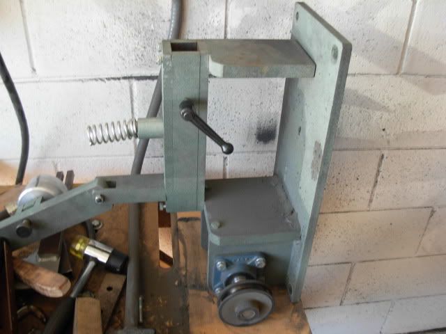
Start by lifting the grinder on end to gain access to the bolts underneath the base
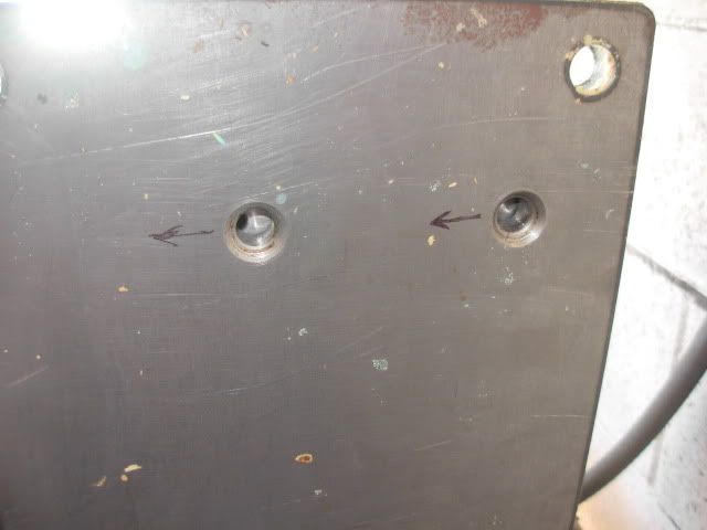
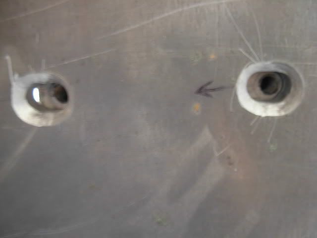
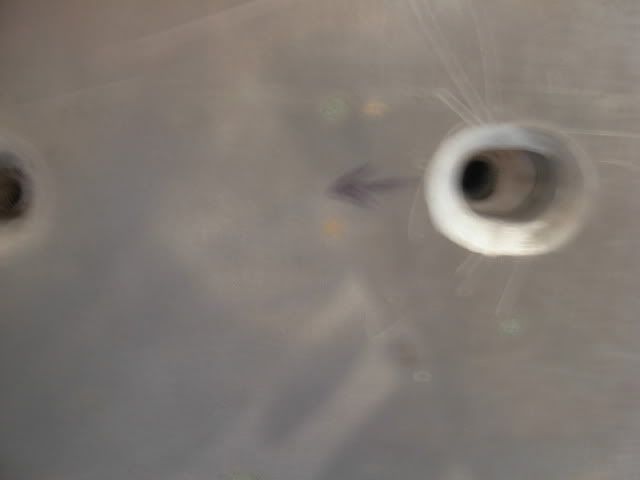
Now before going too far I put a couple arrows near the holes that needed slotting just to avoid any mistakes between disassembly and the mill.
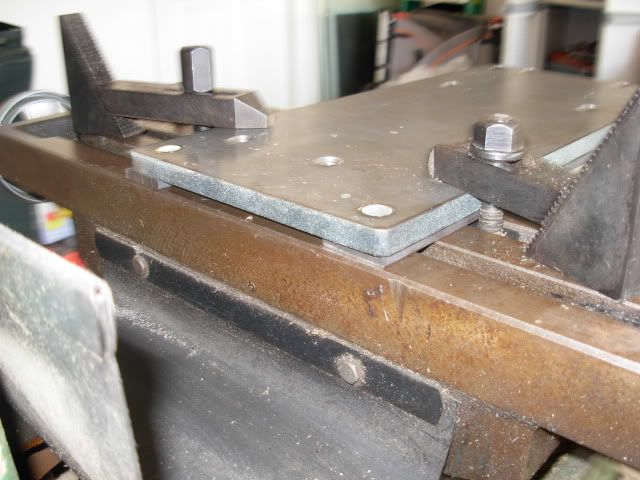
Here's the base clamped down to the mill table with two pieces of 1084 underneath to jack the base up off the table and avoid milling into the table itself
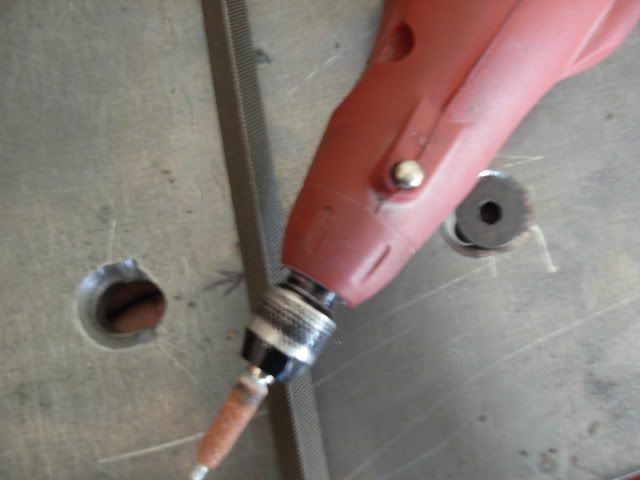
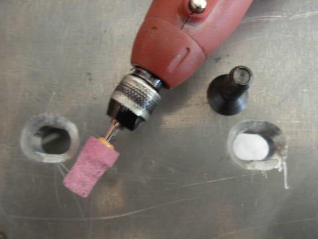
I'm NO crack machinist so I basically just milled the slots roughly 1/2" long which was no problem. My only problem at this point was not having any type of bit to make the countersink with so I just freehanded it starting with a square file to remove some bulk then grinding it the rest of the way with a dremel and a chaisaw sharpening grindstone
After that I cleaned up the countersink a little more with a larger stone
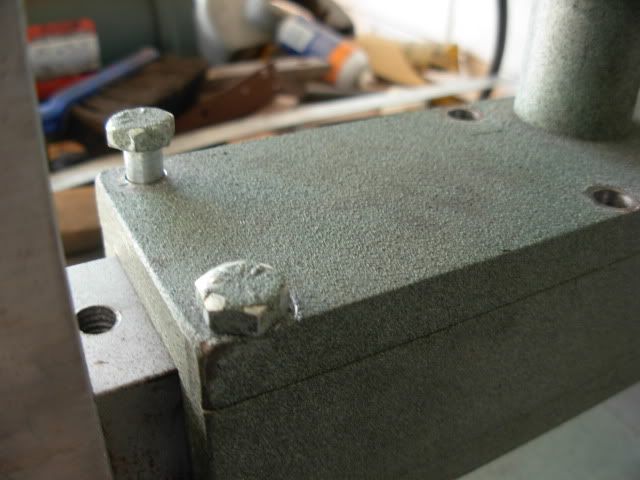
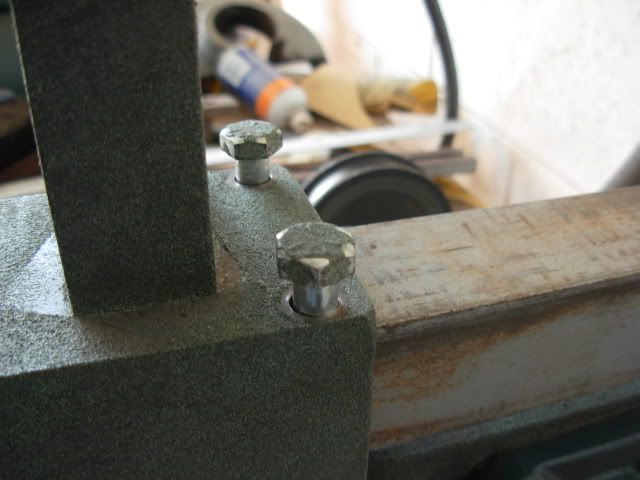
These next two pics were taken with the base re-mounted to the grinder with all the bolts except these two just to demostrate how the much adjustment I can make to the front leg
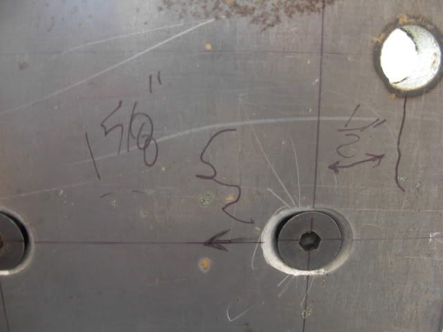
I did this little layout so I could easily locate the slots on the bench surface. I had planned to drill a couple 2" holes through the bench so I could adjust/tighten these two bolts with the grinder mounted but in doing the layout I found that one bolt would land overtop of the framework for the bench so it was a waste of time.
With the bottom end of the machine all bolted back together I wanted to use that "play" as a fine adjustment to square the tooling arm reciever with the driveshaft and get everything tightened back down before re-bolting the grinder back down to the bench.
To do this I put the four corner bolts in and got them started and just snugged the one front bolt so I could shift things around to my liking.
Here was my method for squaring. Insert tooling arm all the way and clamp a combination square to the back side and eyeball square on the ends of the driveshaft. It's kind of difficult to see this clearly so I used some yellow post-it notes as a backround

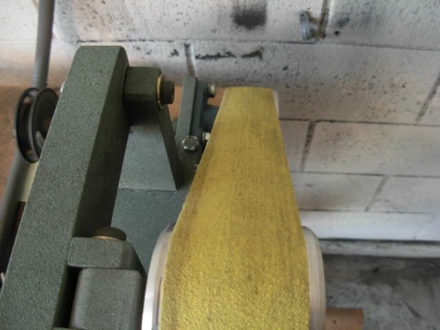
Now I've got ALL the wheel axles parallel it's time to get the centerlines of the wheels all in line. One thing that has been annoying to me that I have never fixed is the fact that when the belt was centered on the platen it was on the left side of the tracking wheel which became a PITA when you wanted to track the belt off the left side of the platen. This being the case I want the belt to track dead center on my tracking wheel so I put a belt on and tracked it to the center to see what I needed to do to the idler wheels and drive wheel to get everything straight.
You can barely see the drive wheel being out about an 1/8" too far so I moved it in to match the centerline of the tracking wheel.
Thats all the pics I got today but my idlers wheels needed to be moved out approx. .100 to bring them into allignment so I put flat washers between the platen and tooling arm to bring the wheels out. They still aren't absolutely perfect but they're out probably .010 too far so I'll probably surface grind the washers to bring them back in just a little.
One more small annoyance that needs fixing is the platen's allignment to the idler wheels. The holes in the angle for the platen mounting bolts are a little oversize to give some adjustment but it's not enough to get perfect allignment so tomorrow I'm gonna re-mount my mill vise and turn those holes into slots to allow a wider range of movement.
Everyones comments and suggestions for further improvement is welcomed and appreciated.
Take care, Josh
This thread is great reading for both KMG owners and those who are building their own grinder. Pay perticular attension to posts # 15 & 16 for a great explaination of the allignment issues at hand-
http://www.bladeforums.com/forums/showthread.php?t=831688&highlight=kmg+tweaks
This thread got me taking a closer look at my own grinder and quite obviously I had the same problems- Axles of the drive, tracking, and idler wheels NOT parallel and centerlines of wheels also misalligned.
I did quite a bit of looking at the grinder sizing up the situation and thinking about what the actual problems were and how to correct them and here's what I came up with-
The part of the puzzel that seemed the hardest to modify in any way was the driveshaft so squaring everything else off the driveshaft was my approach.
The wheels mounted to the tooling arms were in fact perpendiclar to the tooling arm itself so squaring the tooling arm (when tightened) with the driveshaft makes the idler wheel axles parallel to the driveshaft.
There are 8 bolts that go down through the tooling arm reciever that hold the entire top end of the machine together. There is some play in the holes for these bolts so if someone didn't want to permanently modify their machine they CAN loosen these bolts to use that "play" to change the allignment between the tooling arm and the driveshaft. On my grinder doing this gave me approximately 50% of what I needed to get to square so further modification was needed.
Because of that "play" in the bolt holes I figured I could mill out the holes for the front "leg" mounting bolts to make them slots instead of holes to allow a range of adjustment to get the tooling arm reciever squared with the driveshaft. At this point a complete tear down became needed to get any further so I unbolted the grinder from the bench and got to it.
Start by lifting the grinder on end to gain access to the bolts underneath the base
Now before going too far I put a couple arrows near the holes that needed slotting just to avoid any mistakes between disassembly and the mill.
Here's the base clamped down to the mill table with two pieces of 1084 underneath to jack the base up off the table and avoid milling into the table itself
I'm NO crack machinist so I basically just milled the slots roughly 1/2" long which was no problem. My only problem at this point was not having any type of bit to make the countersink with so I just freehanded it starting with a square file to remove some bulk then grinding it the rest of the way with a dremel and a chaisaw sharpening grindstone
After that I cleaned up the countersink a little more with a larger stone
These next two pics were taken with the base re-mounted to the grinder with all the bolts except these two just to demostrate how the much adjustment I can make to the front leg
I did this little layout so I could easily locate the slots on the bench surface. I had planned to drill a couple 2" holes through the bench so I could adjust/tighten these two bolts with the grinder mounted but in doing the layout I found that one bolt would land overtop of the framework for the bench so it was a waste of time.
With the bottom end of the machine all bolted back together I wanted to use that "play" as a fine adjustment to square the tooling arm reciever with the driveshaft and get everything tightened back down before re-bolting the grinder back down to the bench.
To do this I put the four corner bolts in and got them started and just snugged the one front bolt so I could shift things around to my liking.
Here was my method for squaring. Insert tooling arm all the way and clamp a combination square to the back side and eyeball square on the ends of the driveshaft. It's kind of difficult to see this clearly so I used some yellow post-it notes as a backround
Now I've got ALL the wheel axles parallel it's time to get the centerlines of the wheels all in line. One thing that has been annoying to me that I have never fixed is the fact that when the belt was centered on the platen it was on the left side of the tracking wheel which became a PITA when you wanted to track the belt off the left side of the platen. This being the case I want the belt to track dead center on my tracking wheel so I put a belt on and tracked it to the center to see what I needed to do to the idler wheels and drive wheel to get everything straight.
You can barely see the drive wheel being out about an 1/8" too far so I moved it in to match the centerline of the tracking wheel.
Thats all the pics I got today but my idlers wheels needed to be moved out approx. .100 to bring them into allignment so I put flat washers between the platen and tooling arm to bring the wheels out. They still aren't absolutely perfect but they're out probably .010 too far so I'll probably surface grind the washers to bring them back in just a little.
One more small annoyance that needs fixing is the platen's allignment to the idler wheels. The holes in the angle for the platen mounting bolts are a little oversize to give some adjustment but it's not enough to get perfect allignment so tomorrow I'm gonna re-mount my mill vise and turn those holes into slots to allow a wider range of movement.
Everyones comments and suggestions for further improvement is welcomed and appreciated.
Take care, Josh
Last edited:
")