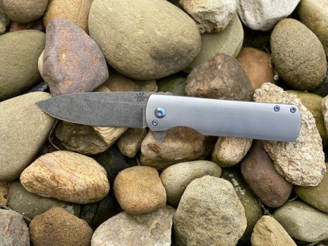
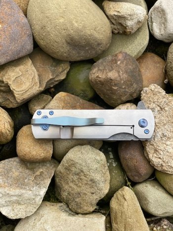
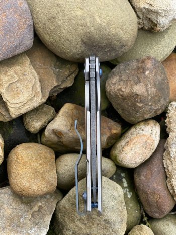
Small Batch Run of MagnaCut frame locks

JRB Blades

Well-Known Member
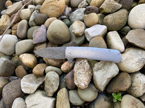
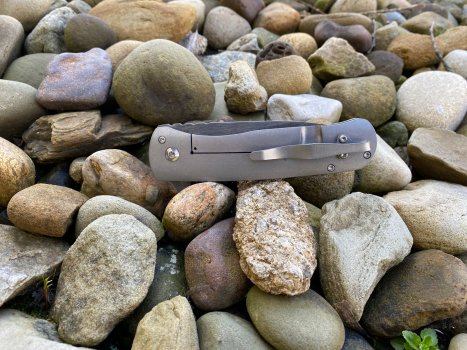
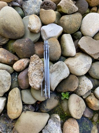
Starting a thread to show the progress on my small batch run of frame locks. Making 7 knives total. They will all have .125" MagnaCut blades finished to about 63-64 Rockwell. I'll have 4 of the Gator model with .135" titanium scales and 3 of the Fighter model with .140" scales. I'm gonna try to include pictures and details of what/why I'm doing certain things.

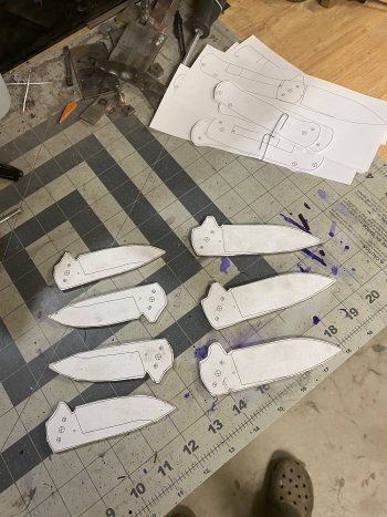
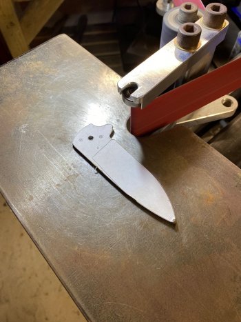
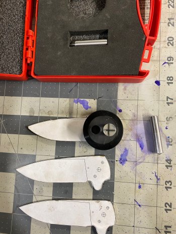
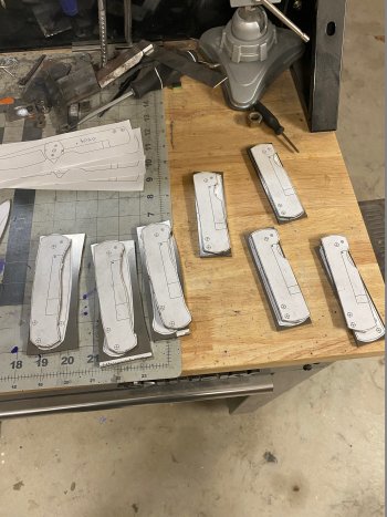
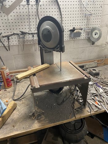
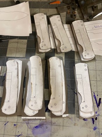
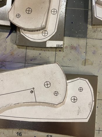
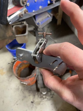
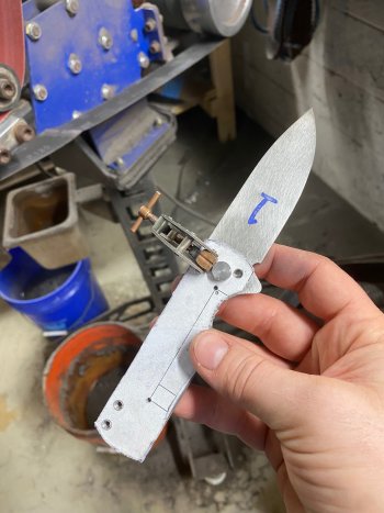
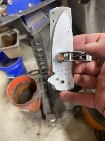
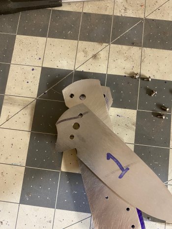
Nothing too exciting yet... First step was to glue up my blade templates and cut them out on the band saw and then rough grind them to shape with an 80 grit belt. I left some meat around the template so that once I get the scales to their final shape, I can install the blade and make sure that my lines are flush between the blade and the scales in certain areas. It'll make more sense once I get to that point in the build. Tonight I'll refine the shape with a 120 grit belt and try to get the pivot holes drilled and reamed.
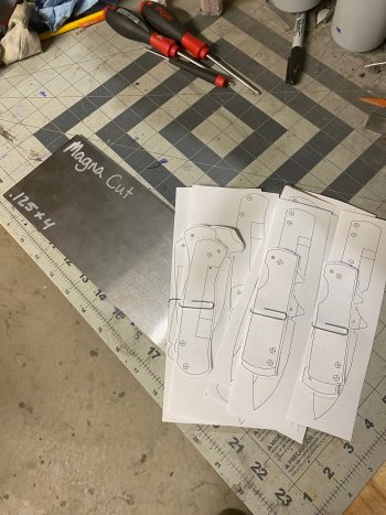
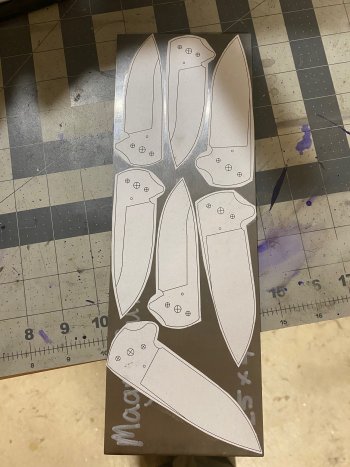
IMG_8901.jpgIMG_8902.jpgIMG_8903.jpg
 
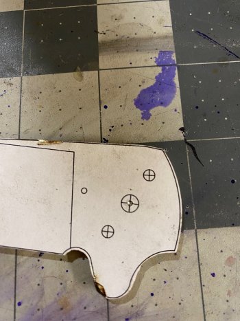
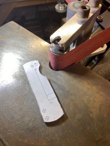
So last night I was able to grind the profiles of the blades up to 120 grit. I used my small wheel attachment with the 1/4" small wheel to get into the small spaces around the flipper tab.
IMG_8913.jpg

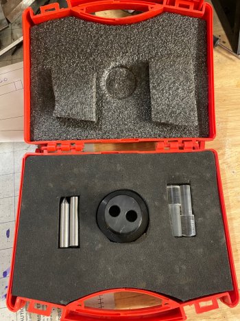
After that I used the optical center punch to mark the center of the pivot so that my pivot holes was as close to the template as possible.

IMG_8909.jpgIMG_8910.jpg

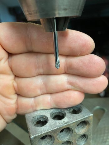
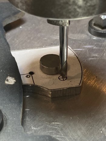
Then I used a 1/8" spot drill to start my hole since my other bits tend to wander even with the optical center punch mark.

IMG_8911.jpg

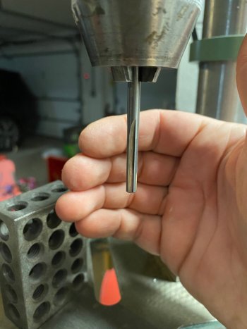
After using the spot drill I opened up the pivot hole with a #15 drill bit and reamed to size with a 3/16" chucking reamer.

IMG_8912.jpg

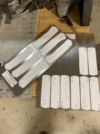
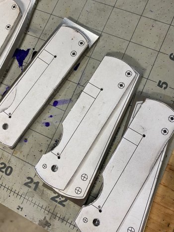
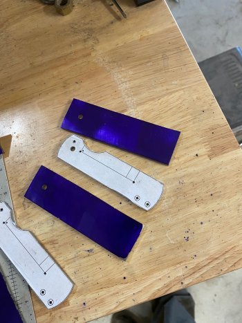
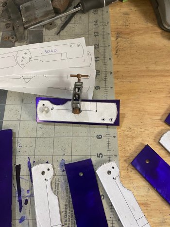
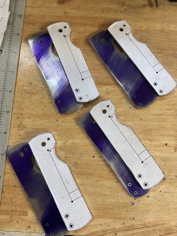
Finally I got the handle scales templates glued up on the titanium sheets.

IMG_8914.jpg
 
Last edited:
That's a lot of work there! Thanks for sharing, love seeing the pics.

Are you running these on washers or bearings?

Thanks! I've never done more than two at one time, so it is definitely time consuming! The only reason I'm doing 7 at a time is I don't have the ability to properly heat treat MagnaCut and definitely don't want to to this steel a disservice, so I'll be sending them to a professional for heat treating. It's cheaper the more you send, hence the small batch.

I'll be running these on Skiff ball bearings I think. I have made a few with PB washers, and I really like them. It is a bit more difficult I think to mill out that .042" bearing pocket and have it perfect on each scale, but I feel like I get better action with the bearings than I do the washers. Could just be all in head though.
 
Last edited:
Thanks! I've never done more than two at one time, so it is definitely time consuming! The only reason I'm doing 7 at a time is I don't have the ability to properly heat treat MagnaCut and definitely don't want to to this steel a disservice, so I'll be sending them to a professional for heat treating. It's cheaper the more you send, hence the small batch.

I'll be running these on Skiff ball bearings I think. I have made a few with PB washers, and I really like them. It is a bit more difficult I think to mill out that .042" bearing pocket and have it perfect on each scale, but I feel like I get better action with the bearings than I do the washers. Could just be all in head though.
Cool yeah I do the same thing! Washers are very finicky and require super precise tolerances to get them smooth with no play....I've thought about switching to skiff bearings myself!
 
Looking good so far, I will be following along. A tip for you that is better/stiffer than the spotting drill is a center drill for a lathe and they are cheap.
 
Had a productive weekend working on these framelocks. Due to my day job, most progress will be made on weekends and there will be a huge photo dump/post on Monday!

First step this weekend was to get the lockside of the handle scales cut out. Love the Swag table with my portaband, makes it a lot easier! I'll explain why later that I don't cut out both sides at the same time. Again, just got them roughed out and will grind to shape on the belt sander. I don't go right to my lines, that'll be for later.

IMG_8922.jpg

IMG_8923.jpg

IMG_8924.jpg

IMG_8925.jpg

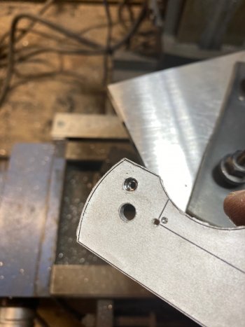
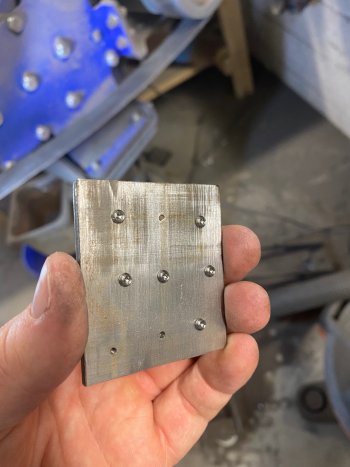
Next, I again use the optical center punch to mark the center of my pivot, through holes for the stand-off screws, detent ball, and the upper corners of my lockbar. If the upper corner of the lock bar holes aren't drilled, it would be very difficult to get the cut to stop in just the right place since I use a dremel type disc in my mini mill. I will also mark the pivot on the show side scale as well.

IMG_8926.jpg

I don't mark the stop pin hole right now, that'll be done using the DRO on my mini mill in order to get the stop pin in the exact location that I need it to be.

IMG_8927.jpg
 
Next, I drill the holes in my lock side scale. I use the spotting drill to mark the pivot hole, follow that up with the #15 bit, and finish up with a 3/16" chucking reamer. The through holes for the stand-offs will be drill with a #44 dill bit. I use a 5/64" bit to drill the corners of the lock bar. I don't drill the detent hole at this point. I could, just don't yet.

IMG_8928.jpg

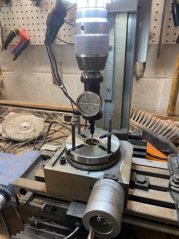
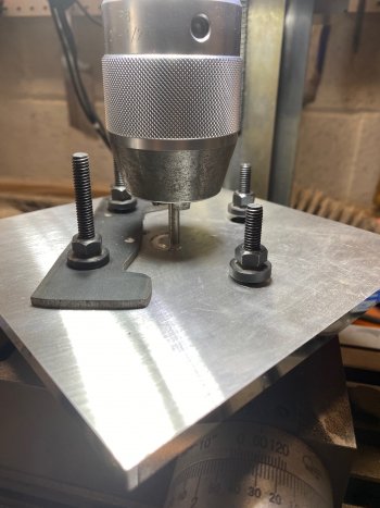
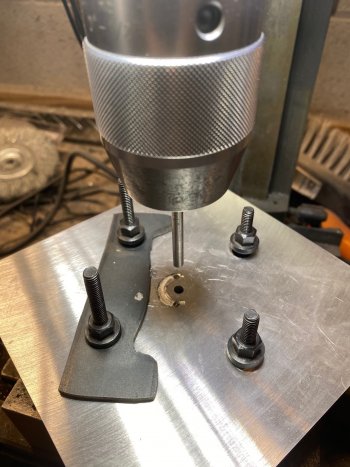
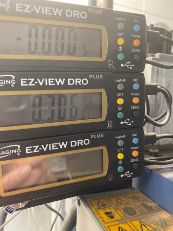
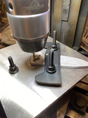
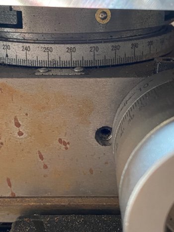
Next, I have to center my rotary table to my spindle using a coaxial indicator. Once the table is centered, I need to center the 1/4" aluminum plate that I mount to the top of the rotary table. To do this, I place a precision ground ground 3/16" rod into my spindle and place it into the 3/16" reamed hole that I have in the center of the aluminum plate. You can see the hold down bar that I have in order to keep the blade stabalized while milling the stop pin track. Once the aluminum plate is centered, I will lock down the X-axis and move the Y-axis .3060 which is the distance from the pivot to the stop pin hole according to my CAD software. Once I have the blade in place, I will mark the location of the stop pin with the spotting drill bit. Once marked, I will drill the stop pin hole with a #44 drill bit. I do this so that I can counterbore that hole for the head of the stop pin screw.

IMG_8929.jpg

IMG_8930.jpg

IMG_8931.jpg

IMG_8932.jpg

IMG_8933.jpg
 
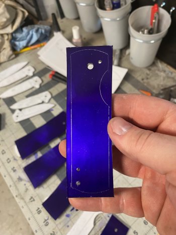
Once I have the #44 hole in the stop pin location of the lock side liner, it's time to get the show side scale going. I dykem to back of the show side scale piece. I then place to pivot through the lock side and into the show side. I then clamp them together with a Kant Twist clamp and scribe the outline of the lock side scale onto the show side. Before separating them, I use the lock side as a template and transfer the stop pin hole and the two through holes for the stand off. Then it's time to cut out the show side. I find that this is the best method (for me) to make sure that all my holes line up on both sets of scales since we are dealing with thousandths of an inch!

IMG_8934.jpg

IMG_8935.jpg

IMG_8936.jpg

IMG_8937.jpg

IMG_8938.jpg

IMG_8939.jpg

IMG_8940.jpg

IMG_8941.jpg
 
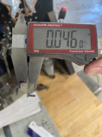
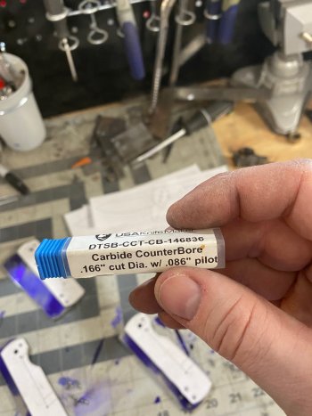
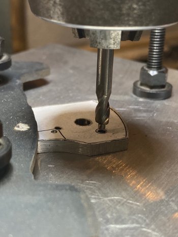
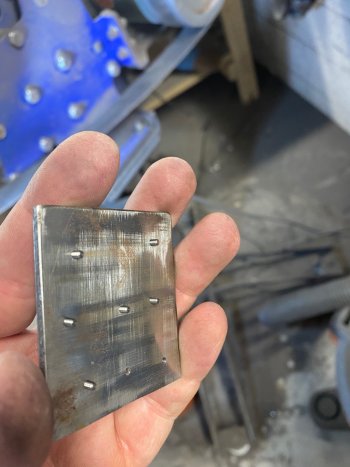
Now that the stand-off and stop pin holes are counterbored, I have to shorten the screws for the stand-offs and the stop pin. As they sit, they are too long and the ends of the screws would hit each other inside of the stand-offs and the stop pin, preventing them from tightening down properly. For this task, I drilled and tapped a scrap piece of 1/8" metal and screw the screws all the way in. Then using the belt sander, remove the threaded portion of the screw that sticks out of the back.

IMG_8942.jpg

IMG_8943.jpg

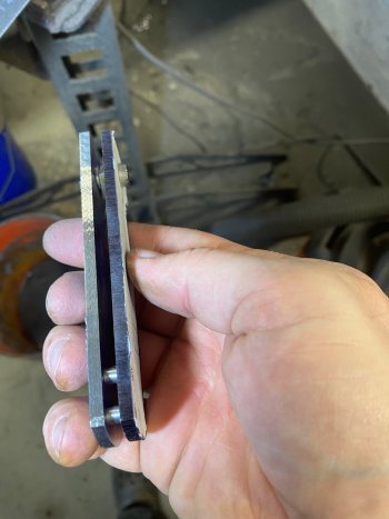
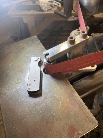
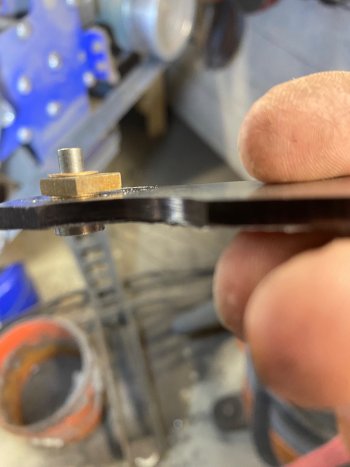
Once the screws are shortened, I can use some sacrificial screws and stand-offs to assemble the handle scales. Because I'll be using caged bearings for the build, I'll recess the inside of the pivot area of both scales and leave a .020" clearance between the blade and handle scales. To simulate this clearance, I use a couple of .020" PH washers sandwiched around a piece of 1/8" scrap steel that has a reamed 3/16" pivot hole. My stand-offs are .165" which accounts for my .125" blade and the two .020" clearance gaps on either side. Now I can profile both scales at the same time to get my final dimensions. I grind these up to 120 grit for now.

IMG_8944.jpg

IMG_8945.jpg

IMG_8946.jpg

Now that the handle scales are to their final dimensions, I need to open up the stop pin hole to its final 1/8" diameter. In order to do this, I place the scales with the outsides facing each other so that I see the #44 hole and not the counterbored #44 hole. I hop that makes sense. I place a pivot through both pivot holes and use 3 #44 drill bits in the stop pin hole and the two through holes for the stand-offs so that I am as aligned as I can get all the holes. I then clamp them together and remove the drill bits and pivot. Finally I use a #33 drill bit to open up the stop pin hole and ream to size with a .125" chucking reamer.

IMG_8952.jpg
 
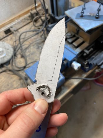
Now that my stop pin hole is to it's final diameter, I can set the open and close positions of the stop pin track on my blade. To do this, I place a pivot through the lock side scale and the blade. I get the blade to the position that I want it to be in when opened. I clap the scale and blade together and drill through the stop pin hole with a 1/8" drill bit. I then clamp the blade in the closed position that I want and clamp them and drill through the stop pin hole again. Now I have the ends of my stop pin track set.
IMG_8953.jpg

IMG_8954.jpg

IMG_8955.jpg
 
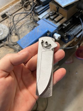
Now it's time to mill the stop pin track. Since the mill is already setup to drill the stop pin hole, it is ready to go for the stop pin track. I place a 1/8" drill bit the chuck and clamp down my blade. I rotate the table until the drill bit fits securely into the pre-drilled hole in the blade. I check the rotary table and mark that number down. I then rotate the table and do the same for the other hole in the blade. Now I have my two stop locations for the rotary table. After that it is just rotating from one number to the next until the track is milled out. I use a 9/64" carbide end mill to make the cuts. Using the DRO, I go down about .010" at a time until the track is done. Do some check on open and stop locations, and looks like we are good to go!

IMG_8957.jpg

IMG_8958.jpg

IMG_8959.jpg


IMG_8960.jpg

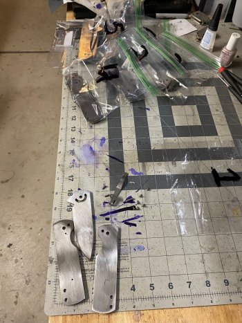
Finally a quick soak in acetone removes the templates. A quick hit on the disc grinder to remove the burred edges and we are good to go!

Next up I need to set the detent hole in the blade and do some spine jimping and these are ready for heat treating!!

IMG_8964.jpg
 
Back
Top