DIY teacher versus store bought

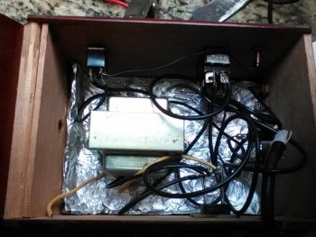
Too low if you using a 24v radio shack xfmr. If you've got it going through a bridge or rectifier, it will be more like 16-17 vdc. Sounds like your coming straight off the xfmr winding or something. Can you open your box and post a pic of the wiring? Maybe with a good pic someone could spot an issue.
 
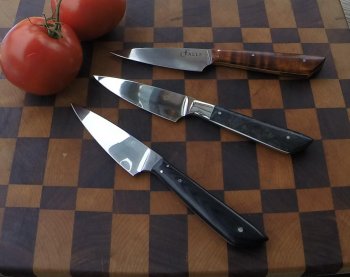
somehow the top one came out but the bottom two are what I usually get even after cleaning all contact areas.
 

Attachments

  • gopr0470.jpg
    gopr0470.jpg
    97 KB · Views: 16
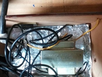
Salt, from the transformer photo it (and from your voltage readings) "looks" like you might be using only the center tap and one side of transformer. See those two yellow looking wirings and the black wire on the secondary (low voltage) side of xformer? Depending on how you've got the diode wired in (single diode or a bridge?) your DC voltage "should" be a tad higher than the AC voltage. Do you have a capacitor wired in? If so, what size in uF?

I see the top knife looks good with the etch - and the bottom two are completely washed out etch wise. You do really need 16 to 19 volts for decent etching - and not dropping much while under load. BTW, is that voltage reading open circuit (not while etching) or under load taken while the pad is down doing an etch? My first check would be to check voltages, both open circuit and load voltage readings.

BTW, your knives look GOOD!!!

Ken H>
 
Salt - from the photo above it looks like you're using a diode bridge with 4 legs sticking up? 2 of legs are marked AC, and 2 are marked DC plus 'n neg? from what I can see, you've got the black wire connected to one of the AC legs and a yellow wire connected to other AC leg? With the one yellow wire hanging loose and not connected? Is that all correct? Do you have the RadioShack part number of your transformer? Looks like it might be a center tapped xformer? That is 12 vac between the black wire and each of the yellow wires? OR - is there only about 6.3vac between the two wires? Check voltage between the not connected yellow wire and the black wire connected to diode bridge.

Do I see a capacitor anywhere in that wiring?

That's a lot of voltage drop and 7vdc is too low for decent etching. Did the xformer have a VA or an amp rating? Is this possibly the xformer you have: 12.6V CT 3.0A CHASSIS-MOUNT TRANSFORMER WITH LEADS Model #: 273-1511? "IF" that is the one you have, AND you're using the yellow 'n black wires, you're only getting half your voltage.

If you pop me an email I'll get the msg on my phone and won't be so long answering.

Ken H>
 
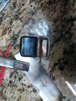
Ken, Salt, that's the right xfmr. The 12-0-12 marking designates a 24v center tap. You guys may have already figured this out privately, I just came back in. I wish I could look at it in person. If you're 100% sure you've got your bridge right, like Ken said, then I'm leaning towards a problem with the leads, a cold solder joint, or bad connection in the marking pad. Hope you get it figured out, stuff like that will drive you crazy.
 
Anthony, salt just confirmed he had the black 'n yellow connected to diode bridge giving him only 12 vac to circuit. I suggested he remove the black wire and connect other yellow wire in place to give 25 vac to diode bridge, and suggested he get a capacitor to have stabilize and smooth voltage in circuit. For the DC portion of etching we don't wish a "pulsing" type DC - better have a smooth DC.

I mentioned to him a loose connection as you suggested could also cause the large voltage drop he's having.

Ken H>

Ken
 
Ken, I mainly use mine on only the 12v tap. I wired mine with a switch to use either 12vac or 24vac input to the bridge, but it worked so good on the 12v position, I don't ever switch it to 24v. Heck, I kind of forgot that I even had that option until I started talking about Salt's problem. Going to 24vac may temporarily help, but I'd say there's still something wrong somewhere.
 
Thanks a lot guys, problem solved. I switched the black wire with the yellow and I can really here the sizzle now. I'm getting a good etch, I just need to hold much shorter cause it can really kill the stencil.
 
I made a etcher from Ernie's plans and a parts list from Chris Crawford Knivers and have always had a problem burning the stencils . After following this discussion I tossed my old Multimeter and picked up a new one test shows 24.2 v on ac and 65 v on dc , no wonder I'm burning up my stencils . I have gone over the wiring diagram and have decided I just don't know. This being the case I've decided to go store bought as opposed to making the stencil makers rich.
 
My stencils would last a long time on 12v, now at 24 they burn up quick but I get a good etch. Wonder if the store bought are any different. I just etch for a much shorter time but the AC seems to hurt the stencil the most.
 
Just be sure not to hold pad against stencil more than a few seconds. What voltage are you showing now on AC and DC? Do you mean "store bought stencils"? OR - store bought etcher?

Fred, just how did you get to 65vdc from 24 vac? The DC voltage can easy gain a few volts, but nothing like over 2 times. Do you know exactly what transformer you're using?

Ken H>
 
I can't believe that I'm going to join this conversation but I am. First, I don't know s*** about electronics but I can follow a schematic. I built my etcher from Ernie's plans and with Radio Shack parts. I have had problems with my etcher from day one. My wand is a piece of maple with a copper strip across the end to hook the alligator clip to and I put a strip of felt across the copper to etch with. I like a really deep etch and in order to get it I have to apply my wand to the stencil for about 20 minutes, no kidding, 20 minutes. I hold it down for about a minute at a time and then let it up to let gas release. I etch with DC output and don't use AC at all. My stencils don't burn up but they only last for 3 or 4 uses. What do you guys think? Thanks,

Wallace
 
Last edited:
Back
Top