Help me I'm in over my head

Lagrange

Well-Known Member
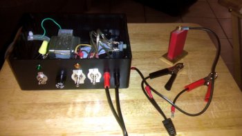
Okay, so I'm building an Etch machine using M. Logiudice's plans and schematics. The thing is, I want to add a set of indicator lights (2) to the double throw switch (DPDT) so when you flip the switch up it turns on a light and when you throw the switch down it turns on a different light.
I need someone with more intelligence than I have to tell me how to wire them in so I dont mess things up.

Please help. Without you, all I will have is an etching machine with two extra unused holes in it.

I have it set up so that to the right of the DPDT swith I have a light above and a light below next to the "ON" positions of the switch.
How do I wire them in using Mr. Logiuduces schematics?
 
I'm not electrically inclined...I would imagine there has to be some power transmitted there. This switch controls the leads for the etcher.
 
I sure wish I could help you out Eric, but electricity is like quantum physics to me, that's why I bought a Personalizer Plus! I so wanted to build my own, but as Dirty Harry says "A man has to know his limitations". ;) Good luck to you bro!
 
OK,you have a double pole,double throw switch,that is two switches in one housing,when the lever is in one position a switch is closed while the other is open. When the lever is moved to the other position that first switch is opend at the same time the other is closed. I'm assuming that in one position the machine is put in the AC mode and in the other position the machine is put in the DC mode and you are wanting to have lights to indicate the mode of operation that the machine is in,is that right?
 
I'm no electrical wizard, but I don't think there is an easy way to do what you are after.
All that DPDT switch is doing is changing between AC and DC.
If you found 2 little lights, one that ONLY ran on AC, and another that ONLY runs on DC, we could do it, but with worries about voltage and power drop.

On second thought, we could probably do it if we replaced the DPDT with a 3PDT or 4PDT toggle.

This schematic, right?
http://www.knives.mlogiudice.com/knifeshop/etcher/electro-etcher_circuit.pdf
 
Last edited:
That is the correct schematic. Calvin and I talked on the phone about this and I think I have it figured out. I thank you all for your time. If I get it up and running I will follow up with pictures.
 
Yep, a 3PDT, and 2 more of the Radio Shack lamps...

Connect all 3 lamps to the SPST switch like already on the schematic.
Connect the main, power indicating lamp just as shown.
Connect the other end of the 2 new lamps to the 3rd pole switched legs of the new toggle. One on one leg, the 2nd on the other, so they are switched...
Connect the center leg of the new toggle to the same point the power indicating lamp connects.

Done.

Edit: I see you have it worked out.
Good luck with the build.
 
I'm glad that the schematic is being put to good use.

It sounds like you've already received some sound advise. Yes, you would need separate lamps: one would be about 12V DC, the other would be 12V AC. I don't think the lamps would draw enough current to affect the etching performance.

Mike LoGiudice
 
The lamps will not draw any material amount of power. I sent you some drawing by email. I hope they help. They are based on a design I came up with for another project when I was building remote control dragsters and need to mark my work a couple of years ago. It is what I use to mark my knives.

Ernie made my logotype base on art work I sent him.

Etcher103-sm.jpgBigBellyFinal2.jpg
 
For future reference, here is what I meant.

Schematic.jpg
 
I personally use 16v transformers. (doorbell)

Experimented a lot with a variac based version and I get the results I like with 16v.
 
Back
Top