How I made a slipjoint "Lemony Snicket"

Sticks

Well-Known Member
I've only made two slip joints, but this is how I made the knife "Lemony Snicket" posted the other day under the "folding knife" sub-forum. I learned a lot and learned that I have a lot to learn... but anyone interested in making a slipjoint should give it a shot. Nice thing is you doun't use much material, so what's to lose...

The list of material includes 1/8" thick precision ground steel. I used CPM 154 for the blade and spring; 304 SS for the liners and 303SS for the pin stock and shield and canvas micarta for the scales.

The pivot pin is 1/8" so I used a No. 31 bit and a 1/8" reamer. The other pins are 3/32 so I used a No. 43 bit and 3/32 reamer.
You need a hard flat surface to build a slip joint. One you can drill holes in to test assemble the kinfe, determine spring pressure, etc. I used a piece of hard wood for the first knife, but for this knife I got a 6" x 12" x 1/2" thick plate of aluminum. It works much better and is worth the investment. Other items I wouldn't do without are a steel protractor, caliper, a height guage, slab of granite (I use a sink cut-out) and probably a few other items I'll think of as I type this.

This knife has a half stop. So the key to designing it was to begin with a perfect circle around the pivot hole. (Thank you Bill Vining for your tutorial, in this forum, on How to Build a Texas Toothpick.) I've tried drafting designs on paper with a compass and ruler, but the problem with transferring the design to the steel, for me, is that I've never been able to drill a hole exactly where I wanted to. And so, if the pivot hole is off by just a little bit, the traced design is well... not much help.

So, I decided to drill the pivot hole first and "design" the knife around it, that way I knew the hole was in the correct place. I used precision ground steel which meant that I had a straight edge at the top and end of the steel. I used those as my constants for scribing all lines. To decide where to drill the pivot hole I first had to decide how "deep" as opposed to wide the back spring would be. Somewhere I read that it should be 1 1/2 times the width. So I figured 3/16". I then decided how large I wanted the "circle" around the pivot hole to be. I divided that in half and added the 3/16" and marked that down from the top edge (and gave myself a little extra depth, which proved to be helpful) and about 4" from the end of the steel.

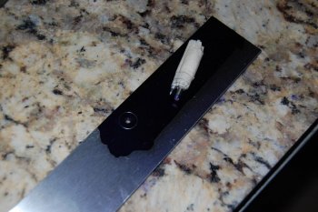
After drilling and reaming the pivot hole, I scribed the circle. The "gizmo" I used is just a lot of masking tape wrapped around 1/8 pin stock with the carbide tip of my scribe.
1.jpg

Actually this isn't the circle I ended up using. It was too small, but its the only one I have a picture of at this stage. After I scribed a larger circle, I used a square to scribe a vertical line touching the back of the larger circle and then a line parallel to the top of the larger circle where the spring will be seated.
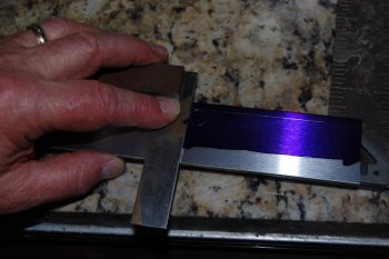
1c.jpg

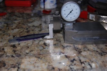
Next I scribed a line at an angle for the kick. In the next picture I have ground the angle for the kick (just touching the circle) and I am measuring the length of the distance of the back of the kick to the parallel line where the back spring will be seated. This measuerment is important to know where to mark the point where the spring will meet the spine of the blade. In other words how long the notch will be.
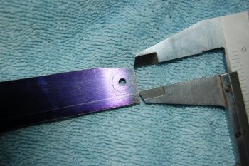
1d.jpg

In the next picture I have marked the "notch" for the spring, which should be about 10% longer than the back of the kick.
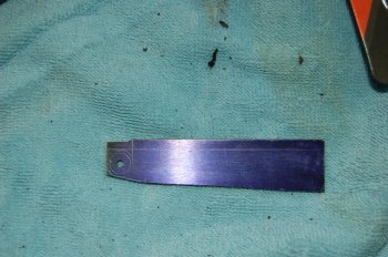
2a.jpg

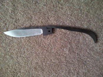
Here I've ground and filed the notch for the spring and have the basic geometry for a half stop slipjoint.
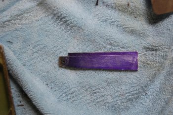
2b.jpg

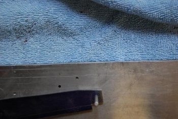
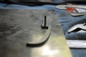
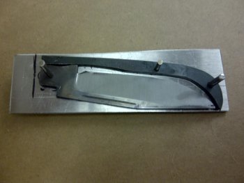
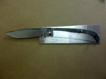
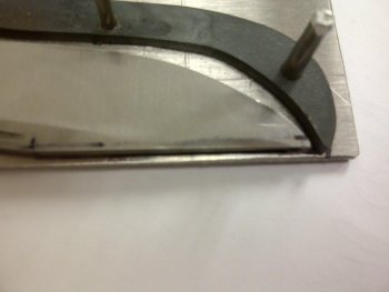
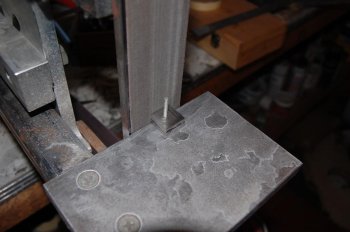
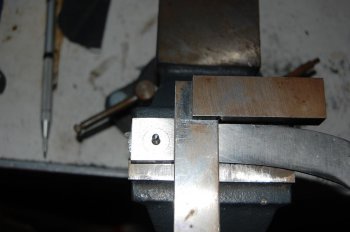
In the next pictures I'm checking to see that the blade will permit the spring to be be flush in the open, half stop and closed position. Really what I'm cecking is to see if the the three surfaces that I ground to the circle are the exact same distance from the center of the pivot hole. I drilled a hole in my aluminum plate. Put the pin stock through the pivot hole and into the plate. I scribed a line along the blade where the spring will sit and rotated the blade making sure that the other two surfaces matched the scribed line This method is simple and I probably should be using a more precise instrument, but it worked for me. The pictures are blurry and I intentionally moved the blade a touch so the scribed line would be visable. And there will always be more fine tuning on final assembly.
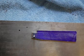
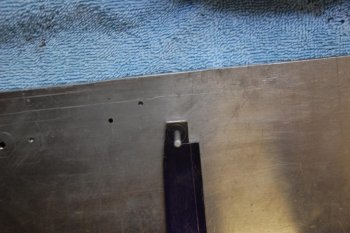
2c.jpg2d.jpg2e.jpg

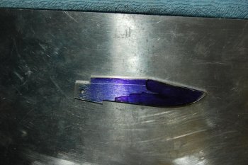
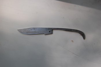
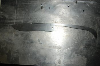
The next two pictures are of the blade design scribed and then the profile ground.
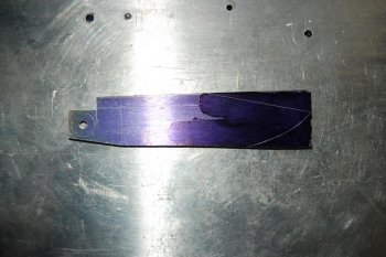
3.jpg4.jpg

Well, now that the easy part is done, and I can't post anymore pictures on this post, I'll take a break.

Jay
 
Last edited:
The last picture I posted is of the blade profile. It is probably understood, but once you have ground to the circle you can't change anything there without effecting the other dimensions. For example, you can't reduce the angle of the kick, grinding into the circle, without grinding the other two an equal amount into the circle.

My next step was to make the spring. I'm sorry I didn't take pictures of it scribed on the steel. Basically I placed the blade kick side up on the same 1/8" precision ground steel that I used for the blade. I drew a parallel line a little over 3/16" down from the top and placed the kick "line" on the scribed line. The straight scribed line on the steel was flush with the straight line of the "closed" kick. I scribed little "bulge", allowing clearance for the blade when closed. This bulge let me drill the hole for the center pin, that sets the spring, without being to close to the spine. Plus, nothing aft of the center pin has any affect on the spring action, so more material there does not affect the performance. The curve for the blade tip just followed the shape of the blade.

5.jpg

In the next pictures the spring is cut and rough shaped. You'll notice it's a kind of "humpity" backed.

DSC_0464.jpg6.1.jpg

Well that had to be fixed. Building slip joints it seems to me is a lot about order of construction, and I'm not sure I had to address this problem at this stage. But, I did because it bugged me. So, I clamped the spring into the notch in the blade where I hoped it would end up someday and super glued them together, over some waxed paper. And I was off to the grinder to fair out the spine/blade. Super glue won't hold for long under the heat of grinding but just long enough for this job.

6.2.jpg
6.jpg

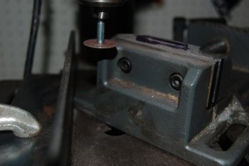
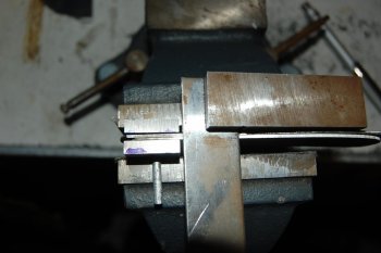
Next step was the nail nick. I don't now how to make a nice crescent shaped nick. Instead, I used a dremel small cutoff wheel that I mounted in my drill press. I don't have a decent picture. I put the blade in the drill press with the spine parallel to the vise jaws, with just enough exposed to permit the cut. I used a piece of angle iron to block the vise so that the dremel bit could not cut deeper than 60% or so of the width of the blade. This permitted the vise to move back and forth but cut to a uniform depth. One lesson I learned is that you need to block how far you want the vice to move back and forth too. Because the dremel bit grabs the steel and you may end up with a longer cut than you wanted or a raggedy end. I only used one dremel wheel on this. Next time I think I'll try a fresh one for the last couple of passed as that may square the ends of the cut.

8.jpg

9.jpg

Now onto the primay grinds. I hollow ground this on a 10" wheel. I think I'll flat grind the next one. But first, to mark the centerlines. I learned after the first slipjoint to mark the cutting edge and the spine. That's the only way I can make sure that the cutting edge and the spine are ground to the center line. That's what you want so that when the finished knife closes the point is in the center.

10.jpg

I marked a line on both sides of the blade that was my target for height of equal grinds. When I grind I hold the blade in my bare hands. Trust me the blade won't get too hot to damage the steel and it slows me down so I don't overgrind.

11.jpg
12.jpg

And now is when the problems begin.
 
Last edited:
Thanks for the WIP, it seems simple enough to follow. I've been dying to try a slippy or frame lock but my lack of mill and surface grinder have put the kibosh on that notion.
 
Mike,

You really should give this a try. I use precision ground or ground steel not sure what the difference is because I don't have a surface grinder. I don't think you'll need that. I've read that Tony Bose doesn't have or use one. The mill is another issue as that is the easiest way to relieve the liners. But if you have an electro-etcher the kind used with a stencil for your mark you can etch the relief. There's a post here somewhere on that. But I tried it and it works. I'll post a picture later.

Jay
 
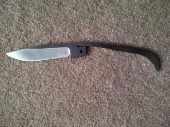
In the last post I included a picture of the blade and spring before heat treat:

12.jpg

I want to make a few comments about this picture. First, you may notice a small radius on the spring where it meets the "springpocket". I did that because I couldn't get the pocket's right angle perfectly clean and its not important that the spring makes an airtight match to the pocket. The only contact points that really matter are at the top of the spine, where it meets the spring, and the back of the blade.

The blade grinds may look okay but they weren't. Chasing symmetry, I ground the cutting edge too thin, sharp really. Especially at about one third the distance from the tip. This may be evident. The grind line rises as it moves toward the tip. I was able to correct that by running the cutting edge along some sand paper until there was an adequate, even amount of steel left at the edge, which also let me work a little on the blade profile giving it an smooth transition.

I also made a triangular cut at the ricasso. I used the smallest triangular file that I could find at the hardware store. I simply filed to the intersection of the cutting edge and flat part of the blade maintaining that angle. That helps later on when doing the final cleanup of the blade. I rolled the fine grit belt over the wheel a bit and the that acted as a stop making a nice even ricasso.

Before heat treat you need to drill the holes in the spring. I used 1/8" pin stock for the butt and 3/32" for the center, drilling and reaming as mentioned above. The placement of the center hole, the one that "anchors" the spring was just a judgment call. I just looked at pictures of other knives as a reference. I think on this knife the hole is a tad too far back. Drill the hole low enough in the spring that it won't be at the top of the handle because this pin will show on your finished knife. After I drilled the holes I put a slight counter sink on each side. This helps when assembling the knive while its under spring pressure.

Another note to me. Most folders have a re-curve cutting into the kick. Frankly, I think it looks better but has a practical use too. When you are fine tuning the blade for flush open, half closed and closed the less material that you have to tinker with on the kick the better. Well lessson to me - grind the recurve in the kick before heat treat. I didn't do that and trying to do it after heat treat is no fun.

Next step - liners. The liners are as important to a slipjoint as the blade and spring. They not only provide the profile for the handle, they are what sets the spring tension that makes the knife a slipjoint.

I used 304 SS. Most don't care for this steel. I'm not fond of it either. But I bought a 12" x 12" sheet of .04", and well, to be kind you might call me frugal, others say cheap. I was determined to use it. The problem with 304 SS is that it is not "free machining", compared to 303 SS which works about as easily as nickle silver. So the 304 caused me some problems. First lesson, I tried to cut the liner blanks out with a hack saw. Ha! The unclamped side bent with the first stroke. Luckily, I have a friend with a metal cutting band saw. Next lesson- don't try drilling 304 with anything but a new good quality drill bit. I pushed a few bits through and the hole resulted in a dimple that had to be sanded out, or in one case caused the scale to bend.

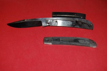
Here's picture of the second effort at liners. The first set were no good because they didn't result in adequate spring pressure. I should have mentioned earlier that the liner blanks are superglued together so that the holes will match. I superglued the spring to the blade, over waxed paper, then clamped the blade and spring over the liner blanks on to my aluminum plate. I drilled the holes through the liners at the pivot on the blade and the butt of the spring.

12a.jpg12b.jpg12c.jpg

A note on how to get spring pressure. Some drill the pivot hole in the liners and center hole with the spring snug in the blade notch and then raise the back of the spring until there is enough tension for a good action then drill that hole. I drilled the blade pivot hole and back hole first (I was going to say butt hole, but this is family friendly forum) and use the center hole to set the tension. There are several methods to decide where to drill the center hole. The simple way is to mark where the spring joins the blade when its not under tension and scribe the bottom. Measure down about 2mm and move the spring to that point and drill there. Another method is to put the liners, blade and spring back on the aluminun plate, pinned at the pivot and butt and use a clamp to compress the spring to the point you like and mark that.

A couple of comments, on the picures. You may notice that the there is a radius on the corners of the kick and "seat". Be careful doing these. The more you take off the less the spring has to travel. If you take too much you lose some of the snap in the action. Do a little at a time. You can also see my after heat treat effort at the recurve in the kick. Not good and took a lot of time.

When you put pressure on the spring a small gap opens where the spring meets the blade and the spring rises a little as shown in the first picture. That rise is ground away on final profiling but the narrow gap remains. It doesn't bother me but the good builders know how to set the spring without the gap. Maybe one will add some advice on that. I traced the lines of the closed knife to help design the handle shape.

This was my second set of liners, but I abandoned them, because I felt I didn't leave enough room for the handle at the butt. Sadly, these had the best spring tension, but it was the third set that I finally went with.

Well I've got to get Hannah from the groomers, more later.

Jay
 
Last edited:
Sorry all about the latest post. I don't know why the pictures didn't post with the text. I used the same method to post pictures that I had in the past.

Jay
 
Well all, I fixed the previous long winded post by using the "edit" feature and re-uploading the pictures. This is starting to become a WIP on a WIP.

Jay
 
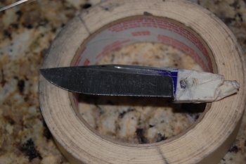
Continuing on. The next pictures are after I have cleaned up the blade, ground the swedge, using the ten inch wheel, and shaped the liners. In shaping the liners, I wanted the curved end of the liner/bolster to be even with the spine of the blade at half closed. And the bottom of the liner/bolster to be even with the cutting edge of the open blade. In the first picture you can see where the balde is dragging on the liners. The liner hasn't been relieved yet. Luckily, I have a friend with a mill who helped me with that.

13.jpg14.jpg

Next step the bolsters. I didn't take any pictures of that process building this knife, but I have enough "spare parts" left to show what I did. The first step was to make sure that the back of the bolsters, when "pinned" through the pivot hole, would be even where they joined the scales. Here I'm using 3/16" 303 ss bar stock. Cold rolled is better I think because it is flatter and doesn't require much sanding for the surface against the liner. I marked each "bolster" so I knew which side was which. Seems odd but that can get confusing. After I figured the general size of the bolsters and had drilled the pivot pin holes, I placed some pin stock in the holes and ground the side that would abut the scales as though they were one piece.

Bolster 1.jpg

At this point, the bolsters are oversize compared to the depth and length of the liners. In other words they hang over the liners by 3/16" or more. I wanted the bolsters to be square with the spine of the knife. So I marked that line on one liner placing the scale side of the bolster against a square held to the spine side of the scale.

Bolster 2.jpg

The to make sure that the bolsters would be even on both sides, I placed one on each side of the liners with a pin through the bolsters at the pivot hole and a pin through the rear hole. I used a square to line up the bolsters and scribed a deep line on the top of the liners where the bolsters were flush against the square. This will be the reference when soldering later.

Bolster 3.jpg

I marked around each "bolster" while held against the liner, on the mark scribed on the "spine" , and then ground each down to about 1/8" or so from the scribed liner outline.

Tinning and soldering. I followed Bill Vining's excellent tutorial in this forum, but this process like peening the pivot, took me several efforts and I was never completly successful. But, things I learned. I won't use 3/16" stock again. It is too thick, takes too long to heat and I ground a lot off anyway. But back to the process. Don't forget to rub pencil lead on anything you don't want the solder to stick to. Solder is funny stuff. It sitcks like the devil to stuff you don't want it to.

I learned to err on the side of using more than less solder. Trying to push too little around to cover the tinned surface doesn't work well. The flux will burn or whatever. If the flux does turn brown you really do have to clean up what you did and start over. If the tinned surface is dull grey rather than shiney, the solder was over heated.

When each liner and bolster was tinned, I clamped them, one liner at a time as in Mr. Vining's tutorial. I used the mark at the top of the scale to align the bolster. I was concerned that as the solder melted the bolster would move off the mark, but it didn't. I learned not to overheat at this point, because later, at the worst time the bolster, will fall off.

I did the rear bolsters the same way.

In shaping the bolsters, and scales, I used the height guage to mark all the way around each liner while it was flat on the granite about a 1/16 " or so. This would be my guide. I'm not good with a slack belt, so I used some pin stock to hold the liners/bolsters together and "rolled" them on a 10" for the curved surface of the handles.

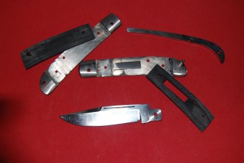
Here's some pictures of the parts, and how they fit together. The liners are mill relieved.

15.jpg
16.jpg
17.jpg

The shield is a bit large and is peened directly to the scale with two pins.

Next adventures in Peening.

Jay
 
Last edited:
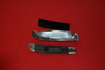
I'll wrap up this WIP with my efforts at peening and a critique of the knife. First, I didn't attempt peening until I had pretty much finished the shaping of the bolsters. I tried to just use enough pin stock on the end bolster and pivot pin bolster to make a small mound at the peen. Too much is a problem. Peening the end bolster is no big deal. I just whacked it like I would a guard or bolsters on a fixed blade knife. That's one advantage to end bolsters. My other slipjoint had wood scales and I was afraid to peen those, thinking they would crack. Since I used micarta on this knife I wasn't too concerned about cracking it. I gave the middle/spring pin a good whack or two and it stays in place. The pin closest to the front bolster isn't peened. The inside is the mill relieved area and I didn't want to mess with that, so it superglued in place.

Peening the pivot hole is something you just have to learn by experience, I think. Here's a picture of the assembled knife.

IMG-20121210-00010.jpg

The pivot pin is visable, but I thought for this attempt at a slipjoint it was peened well enough. Except that it wasn't peened at all. The pin started moving from one side to another, not rotating, just something I could catch my fingernail on. I don't know if I ground, or buffed, the peen out while finishing the knife or whatever.

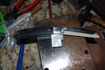
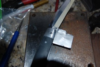
So, that meant I had to poke that pin out and try again. This time I used a small counter sink to bevel the hole. I gently peened the pin, using a piece of heat treat foil between the tang and liner, until each peen was a smooth mound extending well over the hole.

DSC_0510.jpgDSC_0511.jpg

Then I took out the foil. The blade had more play than I wanted. So, I gave it one more blow... and it was too tight. I used a screw driver, twisting it gently between the scales, to "fix" that. Everything seemd fine and I would have bet anything that I had made the perfect peen, nothing to it. Well Hubris and slipjoints don't mix.

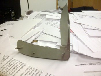
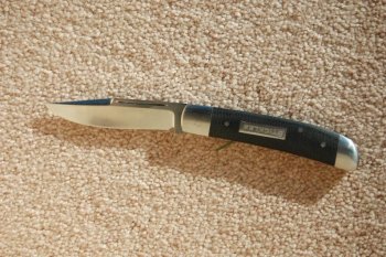
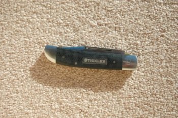
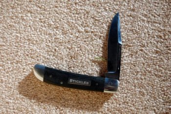
Here's a picture of the finished knife. The pivot peen is notorious.

DSC_0541.jpg

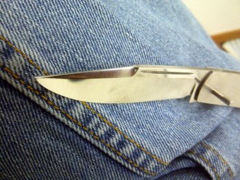
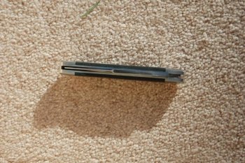
But, the pin isn't moving. I was tempted to keep grinding away with a fine belt to see if the "circle" would disappear. But, when I measured the diameter of the pin it was really close to 1/8", which is what it was before peening, so I decided to leave well enough alone. Here's a few more pics of the knife as "finished".

DSC_0539.jpgDSC_0540.jpgDSC_0543.jpgDSC_0544.jpg

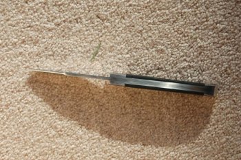
The knife has its flaws. I think the tang is too short. I would like to have had another 1/8" or of tang between the bolster and choil, for my mark (wouldn't have done the shield) and ashthetics. The action is a little lighter than I would prefer. It snaps open and shut, but I would like a little more resistance. I think the "spring pin" is too far back. The nail nick is crude. And too much of the tang is exposed when closed. That's a sharp corner that I think should be less exposed. That may be the result of the spring pocket being 3/16" deep. Well things to work on for the next design which is WIP.

DSC_0505.jpgSlipjoint 3.jpg


Jay
 
Last edited:
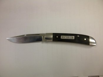
I just saw this work today. I love the grind pattern on this blade. I just ground two small pocket folder blades yesterday with a single grind from edge to back. Your pattern frames the nail nick. Way cool. I may trash my blades and copy this.
 
Thank you Brad and "Wrecks". A lot of knife makers have said that they are reluctant to try a slipjoint. I understand, but honestly, if you can grind to a scribed line you can make a slip joint. It may be too much to expect that your effort will end up like the great makers who post here, but it'll snap open and shut and have a sharp edge. And whose first fixed blade looked as good as a Loveless Big Bear.

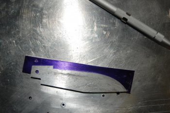
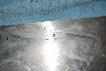
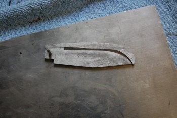
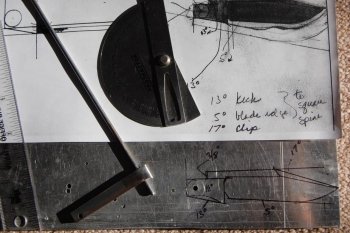
In the pattern that is drawn on the aluminum plate in my last post, there is only one curve, the rest of the lines are drawn (they would be scribed on the steel) with a ruler and compass to measure the angles. The curve is just a trace of the compass. By the way, I wouldn't recommend following this pattern. It makes for a really big blade, over 3.25" long and very deep, making it difficult grind so that the top of the bevel is anywhere near parallel to the nail nick while intersecting with the swedge, "framing" the nail nick.

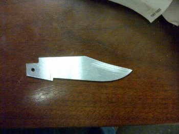
I wouldn't be candid if I didn't confess that I totally ruined the blade pictured last night while grinding the primary bevels. I don't think I can salvage it. So, I may try a new pattern, less downward angle on the blade and maybe less pitch to the kick. Good thing is you don't use much material with these knives and I hadn't made the spring yet.

Jay
 
I must say I wasn't sure from the title what to expect. But it exceeds my expectations. Very nice piece!! Love the WIP and all the pics. They certainly help to explain a few things I have been scratching my head about!! This one is bookmarked for me!!

Excellent work!!
 
Back
Top