You are using an out of date browser. It may not display this or other websites correctly.
You should upgrade or use an alternative browser.
You should upgrade or use an alternative browser.
CNC WIP - small flipper.
- Thread starter BossDog
- Start date
I've managed to assemble 4 flippers so far. One of them I gave to my son-in-law so I'm left with three to tinker with.
The action has been inconsistent between all 4 along with some blade lash open and closed. I spent some time tracking down the issue today.
I started double checking some of my original measurements and math. I found I was off by .010" on the spacer bar. Fixed that and ran a few at different thicknesses. G10 isn't anywhere near flat enough to just set the machine and go. I kept hitting different thicknesses. The solution to getting the right thickness spacer bar for now at least, is to get it close and hand lap it in to where it needs to be.
I also changed my lock up angle from around 8.5-9 degree to 10.5-11 degrees. It was just stupid to try and hit a decent lock up at 8.5 degrees.
Next I'll look at putting together a couple more and then taking a step back and see where I want to go with it.
Todays adventure in CNC is friction welding Titanium.
I dropped (an apparently) dull ball end mill into this Ti to profile out some parts. When you see sparks shoot through the coolant you know something is off. This program had been used several times before with no issues. I'm guessing the ball end mill was pretty dull and the plunge into the material killed it. I'm surprised it didn't just snap. I'm sure it would have soon.
I ground the burr off both sides, threw it back and replaced the end mill. It is cutting fine this time.
Several years ago my wife bought me these "speed out" things. They get screws out that have stripped or broken off. I never thought I would use them until today.
This morning I ran a spotting drill right down into my fixture that had a cap screw in it and it took the entire top of the cap screw off and wrecked the spotting drill.
I can't believe I found these speed out things as normally I would have put them somewhere safe and promptly forgotten about them. Anyway, I did not want to remake the fixture. I dug out some carbide drill bits and drilled out the center of the cap screw and used one of these to get the remaining thread out of the hole. Two steps forward, one step back. It worked and I'm back in business.


This is Doug the opossum that hangs out around the yard and eats bird seed that has spilled to the ground. I gave him a left over thanksgiving dinner roll. He chowed it right down.

This morning I ran a spotting drill right down into my fixture that had a cap screw in it and it took the entire top of the cap screw off and wrecked the spotting drill.
I can't believe I found these speed out things as normally I would have put them somewhere safe and promptly forgotten about them. Anyway, I did not want to remake the fixture. I dug out some carbide drill bits and drilled out the center of the cap screw and used one of these to get the remaining thread out of the hole. Two steps forward, one step back. It worked and I'm back in business.
This is Doug the opossum that hangs out around the yard and eats bird seed that has spilled to the ground. I gave him a left over thanksgiving dinner roll. He chowed it right down.
I had run out of my first batch of parts. I have a 5 of these done and working but I needed to make some tweaks.
Yesterday I spent most of the day redrawing the bevels, thinning the edge and slightly enlarging and extending the stop pin arc in Solidworks. After that I moved it all over to Mastercam and had to realign the Solid part to the fixture. I think this would have been a lot easier with Fusion360 but I don't know that for a fact. Aligning a new model to the fixture was something I hadn't done and had not seen documented anywhere. I finally got that done and then laid out all new tool paths.
I ran the parts and the run time was 3.5 hours - which is insanely, almost criminally long. I went back and made several more changes and now the parts run in 49 minutes. I think I can shave another 10 minutes off that but I'm good for now. Cycle time is not necessarily a priority right now for me.
The top two are blades from today. The bottom one is the "old" style. The bevel goes up higher, the plunge is moved towards the tip a bit, the edge is .005" thinner and the arc is another degree or two longer. I have to run a couple through heat treat to see how straight the edge stays. A lot of guys harden and then mill. I'm not experienced enough to do that yet but it's where I am heading.
Last edited:
CMS3900
Well-Known Member
Looking good Bossdog! I have really been enjoying this thread and it inspires me to try my hand at making a folding knife design I have been kicking around in my head for a while. FWIW, I run AutoCAD and BobCAD, and do a fair deal of subplate work. It helps me to have my fixture plate 3d modeled in a separate drawing that I can save as a new copy, then copy/paste the updated part into. Using a base point as a reference I can snap it to the fixture plate and then send it over to BobCad. I load the drawing, fixture plate and all, into BobCAD so when I run simulations I can see if my fixture is in the way. If I was smart about it, BobCAD lets you save all your operations, so I can basically re-load the program from before, selecting the new geometry and get back to making chips.
That process is how I think it should work. I just hadn't done it before. I need to dig into some more training videos and see what I can pick up from those.
I haven't tried loading a new model while retaining all of the previous tool paths. I know the geometry won't be chained properly but at least I'll have all the feeds and speeds in place.
For the next one I'm going to try it that way.
I haven't tried loading a new model while retaining all of the previous tool paths. I know the geometry won't be chained properly but at least I'll have all the feeds and speeds in place.
For the next one I'm going to try it that way.
Looking good Bossdog! I have really been enjoying this thread and it inspires me to try my hand at making a folding knife design I have been kicking around in my head for a while. FWIW, I run AutoCAD and BobCAD, and do a fair deal of subplate work. It helps me to have my fixture plate 3d modeled in a separate drawing that I can save as a new copy, then copy/paste the updated part into. Using a base point as a reference I can snap it to the fixture plate and then send it over to BobCad. I load the drawing, fixture plate and all, into BobCAD so when I run simulations I can see if my fixture is in the way. If I was smart about it, BobCAD lets you save all your operations, so I can basically re-load the program from before, selecting the new geometry and get back to making chips.


It's time to do some detail in the scales but first I wanted to test a couple settings.
Below shows 2 size ball mills and a spot drill at different depths. A 90 degree spot drill is often used for edge milling chamfers, engraving and in this case cutting a "slot". The are 2 flute and can be run with a chip load several times higher than most other end mills. I find myself using it more and more all the time.
I am looking for how the colors showed up in this multi-layer Ultrex g10.
The colors are black and red and each layer is around .015" thick.
I was pretty sure the ball mills would be the way to go but I found I preferred the spot drill somewhere around .025" deep.
The difference isn't just the appearance, it's the feel as you drag your finger across each one. The ball mill cuts all felt sharp, the spot drill not as much.
The spot drill also seemed to show the color a little better.
I'll try a combination of both in the .015" to .03" depth range.

Doug stopped by for peanuts the squirrels have buried in the snow.

Below shows 2 size ball mills and a spot drill at different depths. A 90 degree spot drill is often used for edge milling chamfers, engraving and in this case cutting a "slot". The are 2 flute and can be run with a chip load several times higher than most other end mills. I find myself using it more and more all the time.
I am looking for how the colors showed up in this multi-layer Ultrex g10.
The colors are black and red and each layer is around .015" thick.
I was pretty sure the ball mills would be the way to go but I found I preferred the spot drill somewhere around .025" deep.
The difference isn't just the appearance, it's the feel as you drag your finger across each one. The ball mill cuts all felt sharp, the spot drill not as much.
The spot drill also seemed to show the color a little better.
I'll try a combination of both in the .015" to .03" depth range.
Doug stopped by for peanuts the squirrels have buried in the snow.
Here is my pile of scrap blades. A couple pieces are mild steel after I got tired of trashing knife steel. Still.
I have more work to do on the tool paths for the blades. There is simply too much clean up and I think I can get them quite a bit better. Also I am starting to understand the difference between a dull and sharp tool in the cuts.

I am managing to get some parts done. Clean up goes a little faster if I can do 2 or 3 at a time. I can't keep track of more than 3 at a time tho, even with numbered trays.

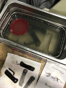
I picked up this ultrasonic cleaner at amazon for around 80 bucks. It has a heater to warm the solution. I also bought a gallon of ultrasonic cleaner but I think it's just diluted ammonia. A buddy has one and just puts simple green in his. Anyway, I like it. The little red cup is a silicon baking cup and I put the screws in there. I thought those wouldn't clean but they do just like the rest of the parts.


I got it because I got tired of cleaning up buff compound. Dump the parts in, hit go, come back in five minutes and then a minute or two with a toothbrush the parts are nice and clean.


I have more work to do on the tool paths for the blades. There is simply too much clean up and I think I can get them quite a bit better. Also I am starting to understand the difference between a dull and sharp tool in the cuts.
I am managing to get some parts done. Clean up goes a little faster if I can do 2 or 3 at a time. I can't keep track of more than 3 at a time tho, even with numbered trays.
I picked up this ultrasonic cleaner at amazon for around 80 bucks. It has a heater to warm the solution. I also bought a gallon of ultrasonic cleaner but I think it's just diluted ammonia. A buddy has one and just puts simple green in his. Anyway, I like it. The little red cup is a silicon baking cup and I put the screws in there. I thought those wouldn't clean but they do just like the rest of the parts.
I got it because I got tired of cleaning up buff compound. Dump the parts in, hit go, come back in five minutes and then a minute or two with a toothbrush the parts are nice and clean.
Attachments

I haven't run the CNC in a couple of weeks. The holidays didn't help shop time and I had a bunch of parts ready to go.
I've completed around a dozen of these so far. I've sold a few and given away a few. I even traded one for one of my older folders from a buddy of mine.
I have a couple left to assemble and then I'll move on to the next design and start the whole thing over again.
I can tell you that it has been a learning process in several ways I did not anticipate. It gave me an opportunity to try different lock face set ups and closed detent set up's. Both of these has always dogged me often enough to be pretty frustrating but when you do one right after the other and modify your process and see improvement, it is very satisfying.
This is the last two of these. I'll be starting a new design next.
I made around 16 of these. Some sold, some given away to pay back old favors, one traded for one of my older folders and the rest I'll just add to my collection until I get another table at a knife show.
I'll start a new thread for the next model
View media item 75

I made around 16 of these. Some sold, some given away to pay back old favors, one traded for one of my older folders and the rest I'll just add to my collection until I get another table at a knife show.
I'll start a new thread for the next model
View media item 75