A Wiring/Electrical question for the group

EdCaffreyMS

"The Montana Bladesmith"
DiverDale's post about the toaster oven, and him saying he's an electrical engineer, prompted me to ask this question.

Some of you know I use an old Ridgid 400 pipe threader, as a hot twister in the Forging shop.
Ridgid-400-cover.png


Because things have to happen so quickly when twisting hot stock, the switch location on these machines (mounted on the right side of the machine) is pretty much useless. You just don't have the time to get the hot stock into the twister, then go around the machine, to to the switch, and then have enough heat left to twist.
So, I wired in a foot switch, according to this diagram, that is in the manual:


KD400-Pipe-Threader-Wiring.jpg
Here's is my problem: With the Forward/Reverse switch on the machine, set to the Reverse position, everything operates as it should. The foot switch turns the machine on/off and it rotates counterclockwise. When I place the Forward/Reverse switch to the Forward position, and then step on the foot switch, I get a hum, and all the lights in the shop "drag down". I've experimented with switching around various wires from the motor to the plug, but still get the same thing.

What adds to my confusion is the following wiring diagram.... it shows that the motor has a blue wire..... mine does not..... rather then blue, I have black, as in the above diagram.


KD400wiring.jpg


I don't know how to make it work with the foot switch in both forward and reverse..... so I've been using it in reverse/CCW only, but it would sure be nice to be able to twist either direction, using the foot switch as an on/off switch. I can follow a wiring diagram, and can usually figure these thing out, given enough time, but this one has had me stumped for a long time. Any ideas or help would be greatly appreciated!!
 
Isn't the diagram on the top wired like the lower right hand pic which is NOT your serial number.

On the top diagram - you are breaking the 'white' at footswitch then to outlet while 'black' heads off to 'change directional rotation'

on the bottom left (YOUR SERIAL NUMBER) the 'WHITE' is used to change rotational direction and the Black would be used to break at footswitch??

I am NOT an EE - just a barefoot pidler
 
That's something I'd not even looked at/considered! I'll tinker and see what I can do..... all too often after being confounded by something, fresh eyes, are what's needed!
 
When you go to FWD and get the hum, the motor is effectively "single phasing" which is like a hydraulic lock where the field has lost it's rotational element and is being held in place, just sitting there drawing amps. That's why it's pulling down your lights. I'm sure you've seen this before when you have a motor that has lost the RUN capacitor and it sits there humming loudly but not rotating. Air conditioners do this all the time.

There's conflicting info in the drawings above, so instead of getting down in the weeds let's start with what NEEDS to happen because I'm sure you can sort it out from there. The foot switch needs to break the NEUTRAL line coming from the 110VAC plug. That NEUTRAL has to be the same neutral for both FWD and REV. Somewhere along the line, that is not happening and I suspect it's where the NEUTRAL is landed on the back of the 4-prong outlet in the drawing that shows the foot switch.

Here's where we get into the weeds. The conflicting info in the drawing above with the foot switch is that the NEUTRAL lands on the outlet. On the correct drawing for your machine, NEUTRAL does not go to the 4-way outlet at all. Your serial number goes to the drawing which has the HOT wire of the 110VAC plug going to the horizontal slot at the 4-prong outlet. The drawing with the foot switch has the NEUTRAL (white wire) from the plug going to the horizontal slot at the bottom of the 4-pring outlet. Yes, the wire says "black" but that's because it's the only other wire coming from the foot switch. (The power comes into the foot switch on the white wire and then they used the remaining wire (black) to come out of the switch, but it's still NEUTRAL).

What I would try:

Lets use the drawing for your serial number. (SERIAL 25922 - 43100 drawing)

1. Disconnect the foot switch and get the machine running correctly in FWD / REV with no foot switch. Verify that your BLUE / YELLOW / BLACK / RED wires go to the correct terminals on the 4-way plug as shown on the SERIAL 25922 - 43100 drawing.

2. Break the 110VAC line coming from the plug to the FWD/REV switch. On your drawing the WHITE (NEUTRAL) from the 110VAC plug goes directly to the center tap on the FWD/REV switch. We want to break that WHITE and run it through your foot switch.


Hope this helps! If I've missed something, please someone correct me. I had a late night being Thanksgiving- with a house full of Filipinos it turned into an all night karaoke party.
 
Isn't the diagram on the top wired like the lower right hand pic which is NOT your serial number.

On the top diagram - you are breaking the 'white' at footswitch then to outlet while 'black' heads off to 'change directional rotation'

on the bottom left (YOUR SERIAL NUMBER) the 'WHITE' is used to change rotational direction and the Black would be used to break at footswitch??

I am NOT an EE - just a barefoot pidler

Greg beat me to it while I was typing!
 
As I quickly read this posting, what caught my attention was reference to switching the neutral leg of the incoming power. You want to switch the hot leg (typically a black wire) in a 120v single phase circuit, never switch the neutral (typically white). The wire colors can easily be crossed between your breaker panel, outlet and equipment making the hot leg connection confusing. Strange things can happen with incorrect wiring orientation. There is a note on the first wiring diagram that references European wiring colors - a hint that you want to not assume anything about what wire colors mean in this case.
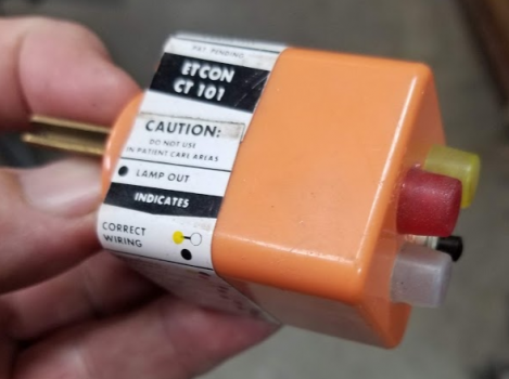
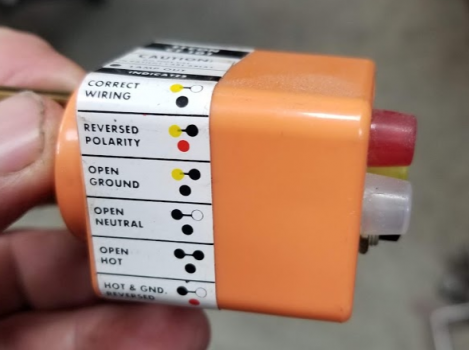
As a basic, first step, to make sure that you are actually switching the hot leg I recommend that you check the incoming orientation of the Hot/Neutral legs at your power outlet. In fact, if you haven't done it, it's really important to make sure all your shop outlets are wired correctly, this can be a big safety issue.
Use one of these:
1606497912137.png
1606498325881.png
Perhaps this is obvious, but, starting and stopping the motor should be as simple as making or breaking the hot leg of the incoming power with your foot switch regardless of the desired motor rotation. As a practical matter, frequently, wire colors "down stream" of the incoming hot leg may be different depending on how internals of the controller were wired, and sometimes different than the manufacturers wiring diagram..
Once you are absolutely sure your incoming power is correct, then look for other problems. As said earlier by others, could be a capacitor, motor windings, or mistakenly rewired reversing switch. One quick check of the motor is to measure the resistance across the windings with an ohm meter, power off of course. The readings should be nearly equal.
Capacity testing: https://www.wikihow.com/Check-a-Start-Capacitor
 
Bob beat me to it - do NOT switch the neutral. As Bob said, break the HOT leg in the cord from recept to machine. Open that circuit and the machine stops, close that circuit and machine starts. That way the foot switch operates as a simple OFF/ON switch. Wire colors don't really mean anything on old equip. As mentioned before, remove foot switch and get machine running correctly in forward and reverse. Then break HOT wire with footswitch.

I can't for the life me me understand why the first dwg shows the neutral being broken with footswitch. Must be a VERY old dwg to even get past UL approval.
 
I agree with switching the Hot wire (for the most part), but as a manufacturer you are not held to those standards and can pretty much do what you want as long as it will pass UL (and I dont know if UL was around when Ed's threader was built?). So if its worked like that since the 50's why wouldn't it continue to work?
 
a lot of old machines switched the neutral. it was a very common practice back in the day particularly with remote pendants which is why the print is drawn that way.
 
Building codes are what put an end to switching the neutral. You don’t want a homeowner changing a lightbulb in a light fixture or a lamp where the socket is still hot when the switch is open. But on industrial machines it was common and it’s still done, even now, in some instances.
 
It's not that switching the neutral won't work, it's what happens when the hot leg is connected to the chassis. Yes, older equipment could have that arrangement, mostly before a 3rd wire ground was required. If you've ever touched a piece of equipment and felt a light buzz or tingling, that indicates the frame is hot and it WILL short to a ground - and if you are part of that circuit... ouch.
In situations with goofy wiring effects, start at the very basic incoming power supply and debug from there.
 
OK folks....my head is swimming now. I get the checks, but once those are done..... ????? Too many directions for me to keep track of.

could someone please take the wiring diagram that shows the foot switch installed.....and explain what to changed there? Come to think of it..... I did see a brief instance of a spark where the motor contacted the frame.....when I had the switch in the Forward position and stepped on the foot switch....... and got the hum/lights pulling down. Maybe getting closer!!

If I'm grasping it.....I could switch the white/black from the power cord, to the switch and outlet??
 
So if its worked like that since the 50's why wouldn't it continue to work?
Good question, all things being equal. But, that kind of reinforces my thoughts on incoming power connections, or failures in the motor or capacitor.
 
could someone please take the wiring diagram that shows the foot switch installed.....and explain what to changed there?
If you look closely at the two versions of the drawing you posted, on the older models the FWD/REV switch was switching the Neutral. On later models it's switching the Hot. (which is what the entire conversation above is about. Rigid must have been listening.) They are using the bottom horizontal slot of the 4-way receptacle as the COMMON. This is important. This is why the wiring of the machine has to match the wiring of the print. You can't mix the two. This is why your motor is locking.

Ed, my recommendation is to pick ONE drawing and do a point-to-point verification that your machine's wiring matches the print. Ignore wire colors. Better yet, use some masking tape and a sharpie and give each wire a number tag. Then mark up the print to reflect which number wire is which so that you can trace it all out later if need be.

Make the machine match the print entirely and make sure it works in forward and reverse. THEN add the foot switch.

The foot switch can interrupt the power to the FWD/REV switch, or it can interrupt the wire going to the COMMON on the 4-way receptacle. Either will work.
 
Last edited:
Awesome!!! Thanks for speaking idioteese for me! :) I think I'm just going to set aside an entire day next week.....and work through it, slowly and methodically as you folks have described. I am really intrigued about the whole idea of polarity issues....that would have never, ever crossed my mind! I will certainly report back.....even if it's just a picture of a smoking hole.....where the pipe threader used to be! :)
 
Back
Top