DoAll G-1 Hydraulic Surface Grinder restoration

Not much pic worthy to report tonight. Finished stripping the back of the machine and decided I'd better get some primer on that bare iron before moving forward.

003_zps72ade65b.jpg


Also began stripping everything off the outside of the cabinet and got that mostly done.

Started assesing what I needed to do to pull the saddle. Looks like I need to remove 3 hydraulic lines, unbolt the crossfeed cylinder from the cabinet, and pull the crossfeed screw to have the saddle ready to lift off. Lots to remove from the underside of the saddle but I've got to remove it to get at it.

-Josh
 
Stripping the cabinet using a 4" angle grinder with a 36 grit flap wheel. Made alot of progress with it and will only have a little bit of chemical stripping to do in tight corners and inside the lettering etc. A heck of a dirty job but getting a good result

001_zps505b83e1.jpg


002_zps841ae043.jpg


-Josh
 
I'm rootin' for you Josh. I know this thing is going to be a workhorse for you when it's done.
 
Appreciate the encouragment fellas :D

Finished stripping the other side of tha cabinet last night

001_zpsc03dc05c.jpg


Cleaned the cabinet with Mineral Spirits and shot it with primer until I ran out.

002_zpse0f3c47f.jpg


I'll pick some more primer and bring my engine hoist home from my inlaws shed today. I can't really put off pulling the saddle any longer so things are about to get a little more interesting

-Josh
 
First step of removing the saddle is to disconnect the hydraulic cylinder from its mounting bracket. Crank the table in until you can just get at the nut, then crank the table out

003_zps53351925.jpg


Now I'm gonna pull the crossfeed screw. The stuff bolted to the front of the saddle is a bear to get out. Flush mounted and a couple layers of paint and rust holding things together. Tapping a razor blade inbetween the two parts is how I get this broken loose

004_zpsb6e366d7.jpg


Once it's broke loose un screwing the screw pulls the flange right out.

005_zps5750646b.jpg


Got my hoist rigged up with a chain hook on each corner of the saddle

007_zpsfd7058ea.jpg


First lift of the saddle to confirm the 3 hydraulic hoses are the only thing connecting the saddle to the cabinet

008_zpsf83b8b1e.jpg


Disconnected the lines on the bottom end

010_zps9f95195b.jpg


And she's free at last !

011_zps460c29c5.jpg


The cabinet under the saddle

012_zpsc175b627.jpg


Picked up an eye bolt thats threaded into the saddle for flipping the saddle over to get access to the underside

015_zpsb1796f8e.jpg


It took a bit of effort to flip the saddle even with the hoist but I got it

016_zps8818b9c4.jpg


One of the main things I want to accomplish is to clean up all the control handles. Getting them all out was a little chore but too bad

017_zps971f4fd2.jpg


Underside of the saddle with the guards removed

018_zps554642de.jpg


I got some primer and paint today along with everything needed for the electrolysis. I'm heavily leaning towards skipping the electrolysis on the saddly for two reasons.

It'll be near impossible to use the hoist to put the saddle in and out of the tank because the hoist's legs are in the way.

The saddle would need to be stripped bare and there's a gazillion hydraulic fittings and lines connected. The risk of damaging anything outweighs the reward of the electrolysis. Instead I think I'll just go at the saddle with the angle grinder and flap wheel which worked great on the cabinet.

That's where I finished up for the day

-Josh
 
Boy I take alot of pics !

I removed this section of the oiler system that delivers the oil to the table ways. Important stuff here that all needs to be repaired or replaced.

From the left is a pressure regulater which seems fine, I've already had it apart, Filter, Manifold that splits the delivery into 3 lines, and oil meters to reduce the flow to the proper amount for the ways.

001_zps79e7f0ff.jpg


This is the filter which I'm assuming has a cartridge inside that can be replaced. No numbers on the filter but I've got DoAll's part number for it. Haven't attempted to take this apart yet but judging by the wallowed out spanner wrench holes it may be a task.

003_zps423a676e.jpg


Here's the right side saddle way. The way oil covers the way and excess drips into the surrounding troff which is shaped so the oil flows around either end and down to the hole which returns the oil to the tank. I've already dug most of the crud out on this side.

004_zps5f650d6e.jpg


Here's the other side... Plugged solid !

005_zps06342d05.jpg


After my initial sweep out this is the pile of crud scraped from the top of the cabinet. I got about 4 of these total.

006_zpse23a1fc5.jpg


This is the coupler that connects the return line to the bottom of the hole in the troff. Yup... plugged full

011_zpsa4df75df.jpg


With the coupler removed from the bottom of this hole and it's still not draining :what!:

007_zpsf9c6892e.jpg


Snaking it out with a coathanger

008_zps6e798f93.jpg


Also pulled a scrap of rag through a few time to get it clean as a whistle. All the clogged up gunk was in the casting and coupler but the line itself was clear.

009_zpsffe9f122.jpg


Cleaned up and ready for primer

013_zpsd2244ca2.jpg


014_zpsab721a9e.jpg


Sprayed with primer

015_zps32688c20.jpg


Snaking the oil meters and couplers from the manifold clean. A paperclip and some brake cleaner cleaned these out spic-n-span

016_zps265dec35.jpg


These were plugged full. Here's the wad of crud that came out of this teeny hole. An .050 hex wrench wouldn't fit through these so they're pretty small

017_zps3364f3c5.jpg


I tried to get a good pic of this. The manifold is actually two pieces. The main body and the threaded nipple screwed into the end. What this pic is supposed to show is that the nipple is threaded in so far it completely covers the first hole. Apperently a real genious was wrenching on this machine at one time and failed to realize they entirely blocked off one of the oilers.

018_zpsbef1901c.jpg


I decided to leave the nipple as-is and just drill a hole through so oil will pass into the meter.

019_zpsea2ab848.jpg


Finished fooling around with those meters and painted the mailbox post while the primer set-up Then shot the whole she-bang with a coat of Rustoleum Smoke Grey paint.

020_zpsa92d9d16.jpg


021_zpsc7b9d59b.jpg


022_zps0e6f6072.jpg


I'm still planning to do the electrolysis but I wanted something real gentle for the handwheels so got some more vinegar and dropped a bunch of stuff in. I took a long time for the stone adapter but it did do a nice job. My handwheels and control levers are in a bit better shape than the adapter so I think it'll work well in a few days of soaking

023_zps8f028834.jpg


Parting shots of the paintjob :biggrin:

025_zpscbcfdb63.jpg


024_zps2bc72230.jpg


-Josh
 
Man, this grinder is looking good. I dearly hope it's clean on the insides but somehow I feel it's going to work like a champ.
 
The plot thickens...

Just got off the phone with DoAll about the filters.

The inline filter pictured above is available for the tidy sum of $144. Ouch. I'd prefer avoiding that but it's not an impossible cost if necessary. Another potential option would be to get this filter apart and remove the guts so it'll just flow through and add in a modern filter in the line.

The in-tank filter assembly is no longer produced and nothing available for replacement elements.

Thinking I may be able to get a useable element for the tank filter once I've got it in hand and can get it's physical measurements. Boy would it be a stroke of luck if a previous owner already updated this filter but I won't know that until I crack into the tank.

The fun continues.... :D

-Josh
 
I wonder if you could adapt a screw-on filter such as an automotive type for the tank filter? My hydraulic press uses one.
 
I'm thinking I can do exactly that Bruce. It should be fine to put the intire unit inside the tank but I'm also thinking it would be nice to plumb it in the line somewhere the filter would remain accessable for easy filter changes in the future. My be too much hassle and better to keep it in the tank though.

My first step is to drain the fluid and open up the tank to see exactly whats in there to work with. Entirely possible the filter is already not original in there or has even been removed completely.

What an ADVENTURE ! Enjoy the rehab more than I anticipated and learning new things along the way :)

-Josh
 
Searching for some filter alternatives online and came up with this filter as a tentative replacement for the inline $144 filter. I've got plenty of open area to reconfigure the layout of the regulator/filter/manifold with a little creative plumbing.

It's not letting me link to the exact one but thinking the second one down on this list- $20.32

http://www.hydraulicstore.com/filtersinline.html

If anyone has any thoughts please share ! :)

-Josh
 
Last edited:
Only got a little shop time tonight but this $144 filter has been bugging me all day. Gotta crack into this thing and see whats inside...

Clamped it in the vise and put some heat to it until I got some liquid boiling from the joint and unscrewed it by tapping one of the holes with a nail set to spin the brass. Came right apart after the heat. Turns out the filter is nothing more than six screens limiting particles from passing through. A glorious version of a kitchen faucet filter screen, LOL

001_zpsa42f9adf.jpg


I cleaned all the screens with soap and water then brake cleaner and cleaned the housing parts with brake cleaner also then reassembled

002_zps7f376bd8.jpg


With a little time left I decided to check up on my vinegar soaking parts. This handwheel is the one that was rusted the worst. It didn't come out nice and clean but a good scrubbing with a small brass bristled wire brush took the softened rust right off. The vinegar is working at the paint also :) Of course the light pitting is permanent but I should be able to get all these parts cleaned up nicely.

003_zps6095ee34.jpg


004_zpsd7e79c78.jpg


Brushed this one off the rest of the way and dropped it back into the vinegar

005_zps9f031c76.jpg


Here we're looking at the hydraulic pump and the suction tube going down into the tank. If needed it looks like I should have room to replumb the suction line and add in a screw on filter right here outside the tank but still on the suction side. This way I'd have easy access for filter changes and have the iol filtered before it gets to the pump.

007_zpsa4fdf512.jpg


That's it for tonight but my luck appears to be running with this machine :D

-Josh
 
I like what you got going Josh. Are you planning on cleaning out the cabinet (last picture)?
 
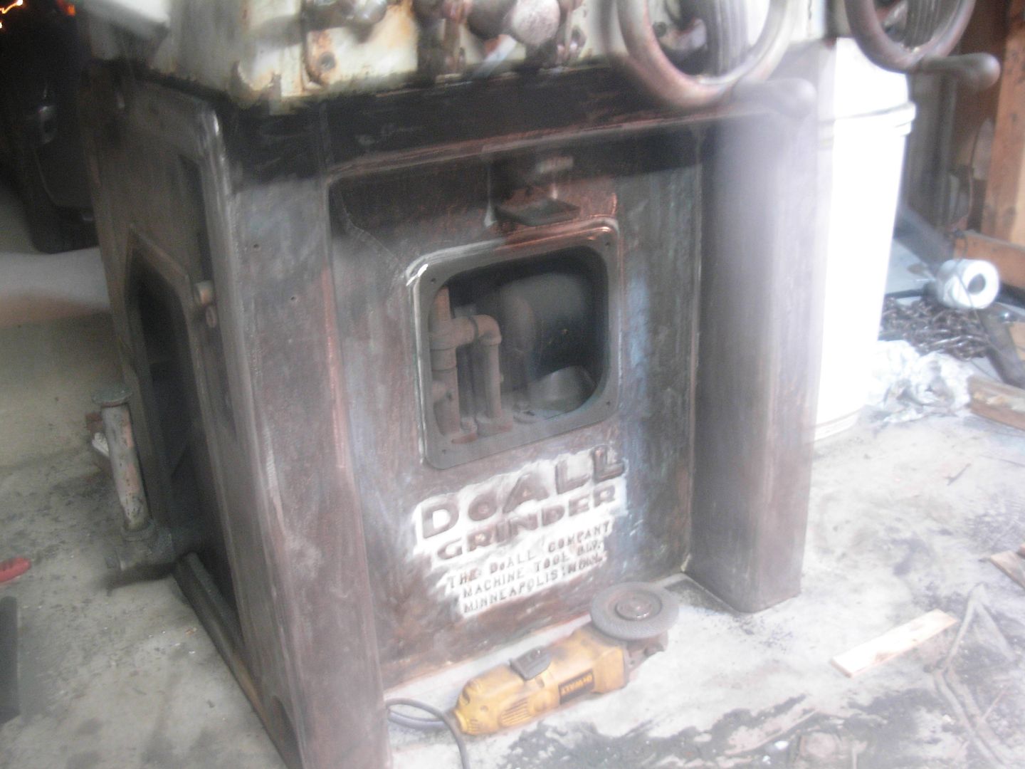
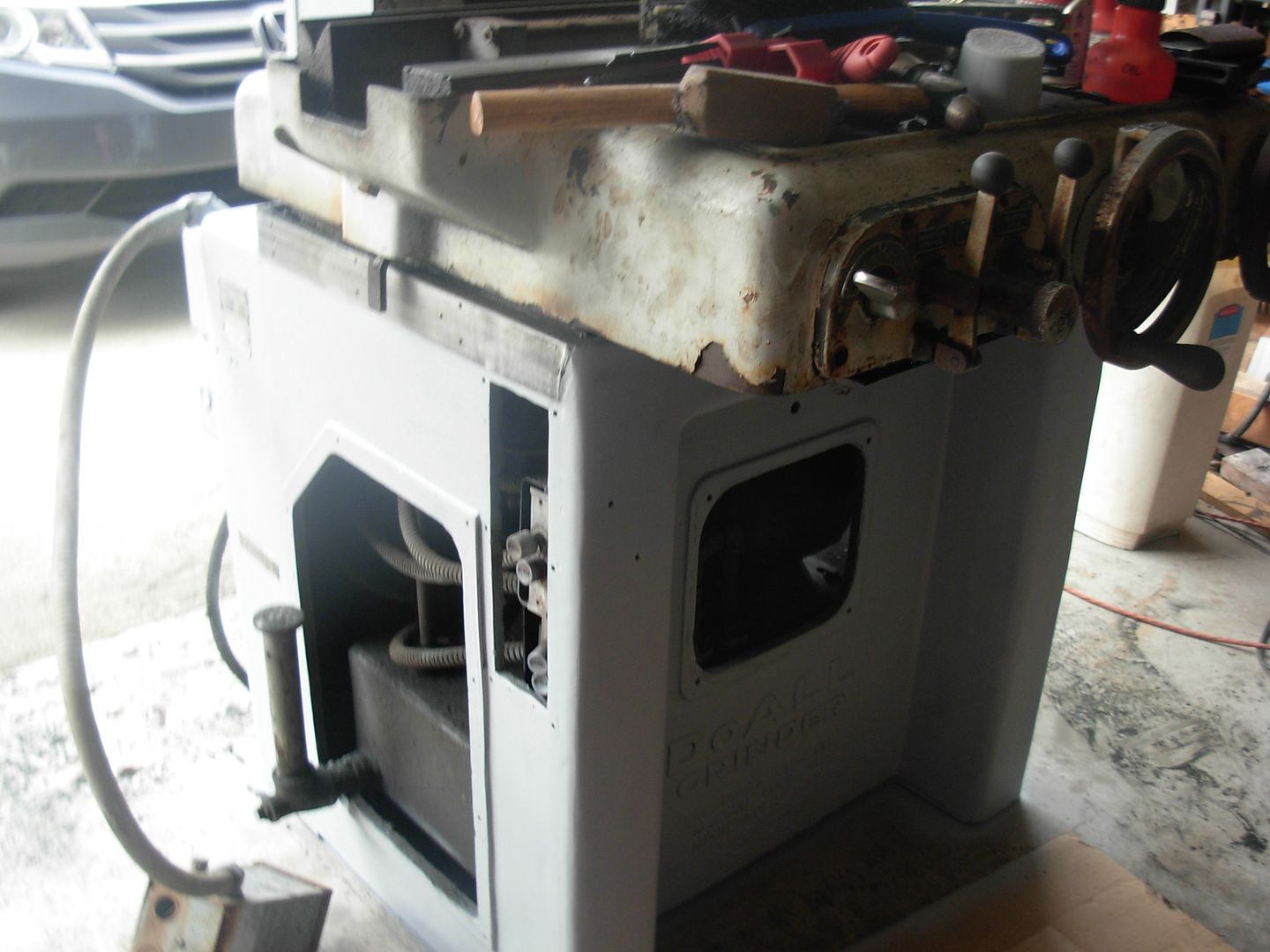
Eric, I'm not planning to disassemble the inside of the cabinet and remove it. I'm planning to just give everything a light degreasing once I get into opening up the tank for cleaning and filter replacement. All appears in good shape in the cabinet just oily and dusty.


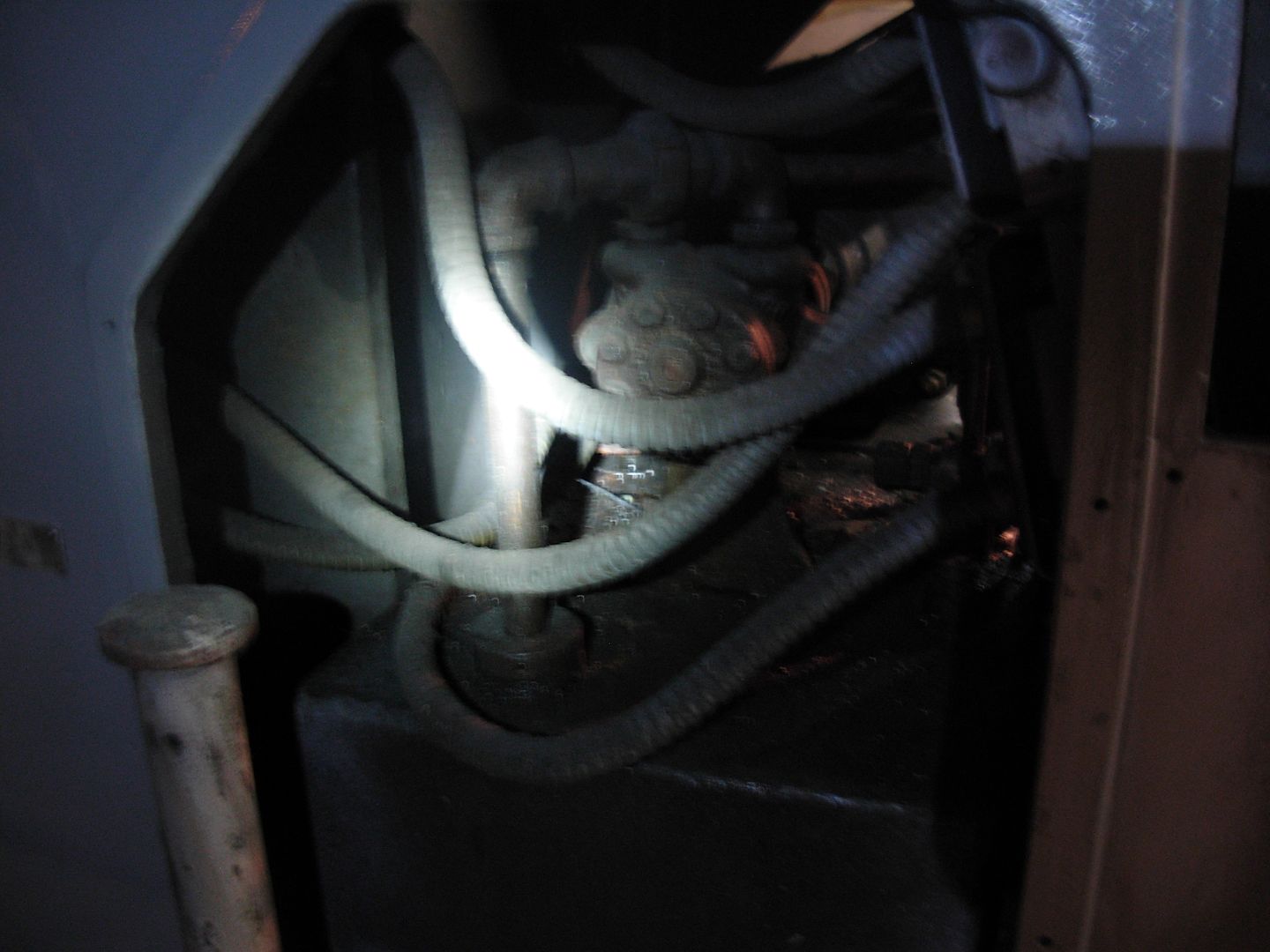
One thing I must do is make absolutely certain my oil passages to the ways are clear. It's evident after removing the saddle that the left side saddle ways are not getting the oil they should.

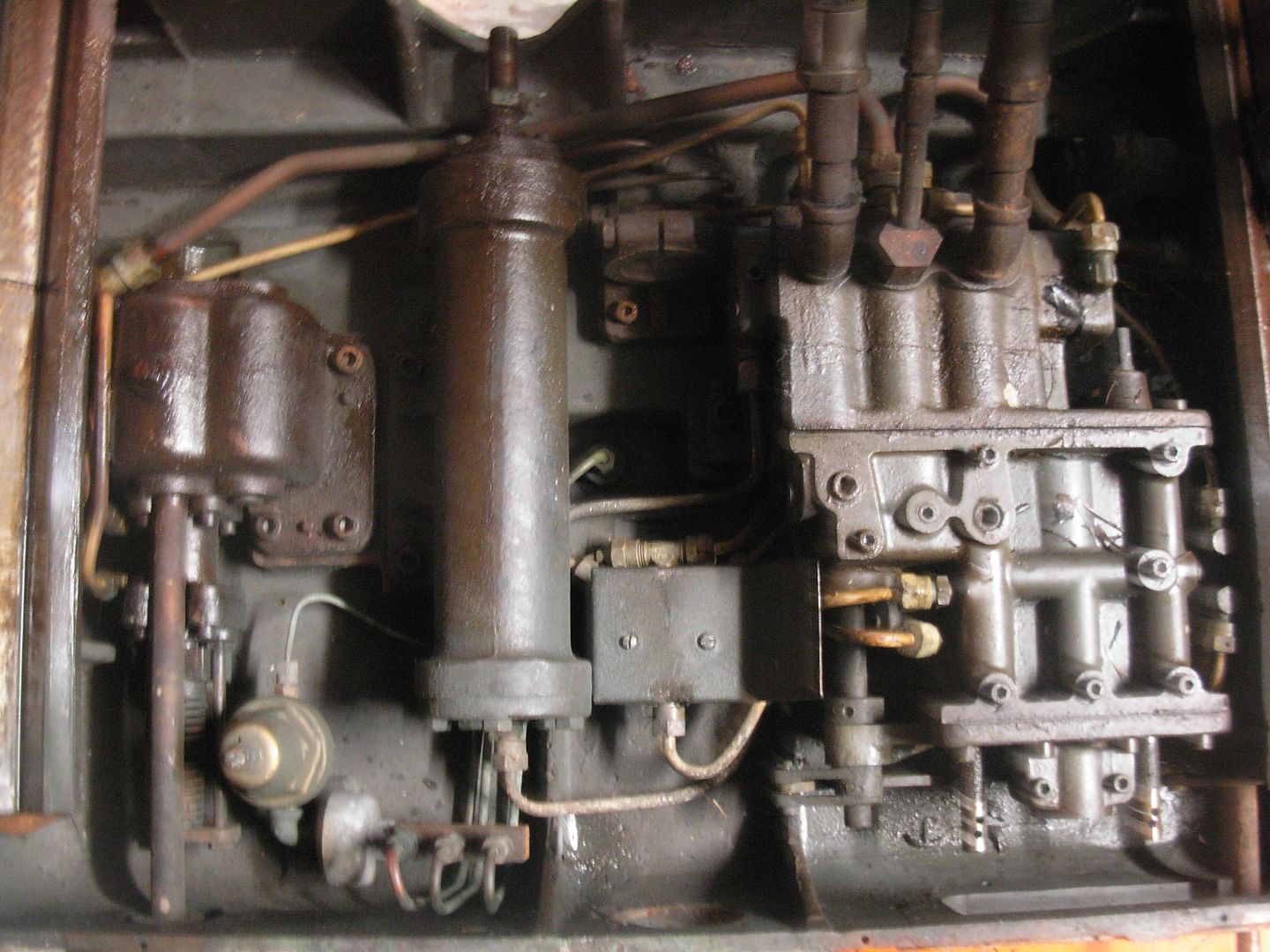
It's taken me a little studying to fully understand how the oiler system operates and I probably never would've got it if not for a small clue found in a thread I was reading about a similar machine. The main point learned there is- There are no oil lines for lubricating the saddle ways.

For proper lubrication of the ways the oil follows this path-

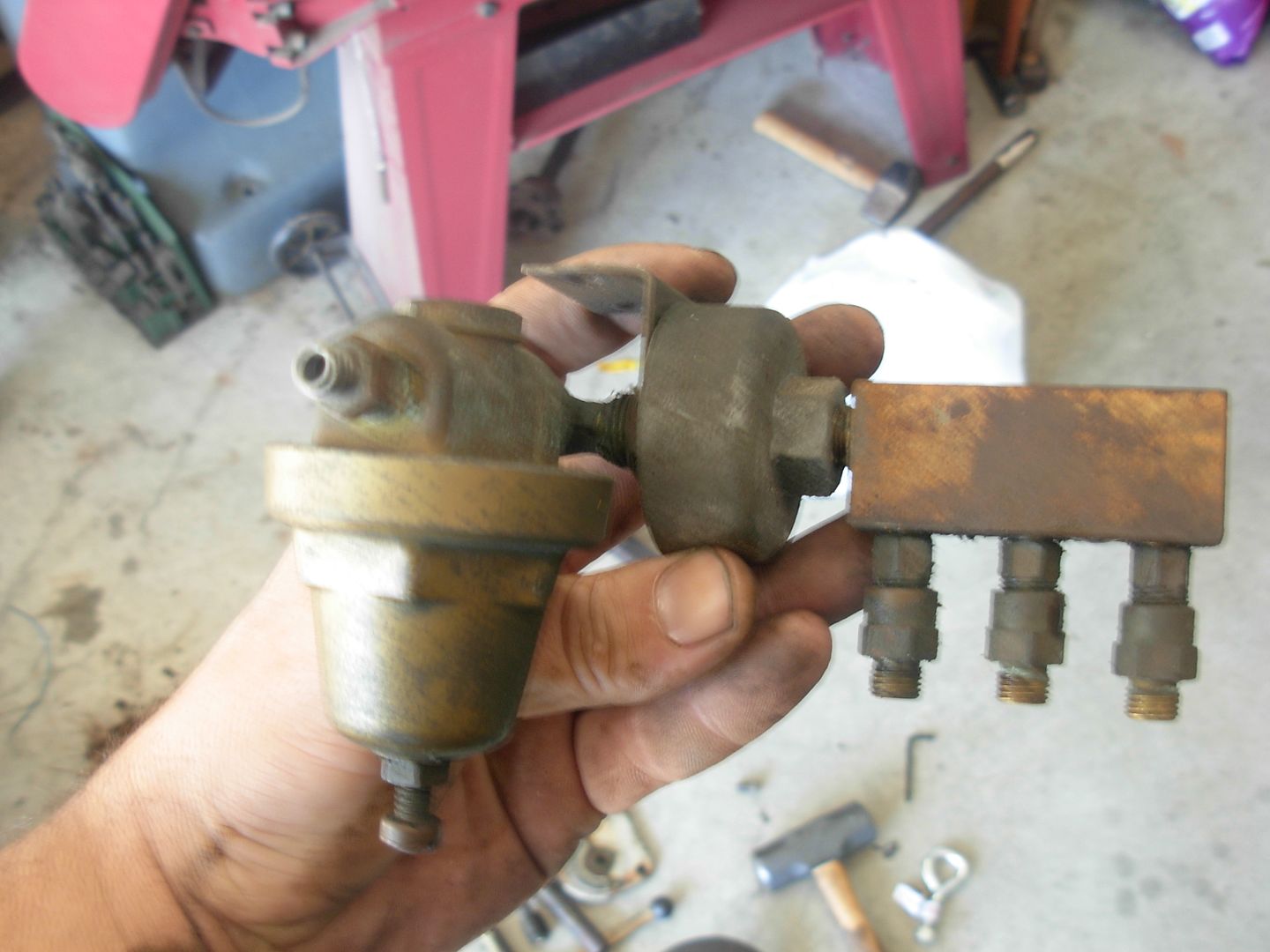
-Pressured supply line from the main combination valve goes to the oil regulator.
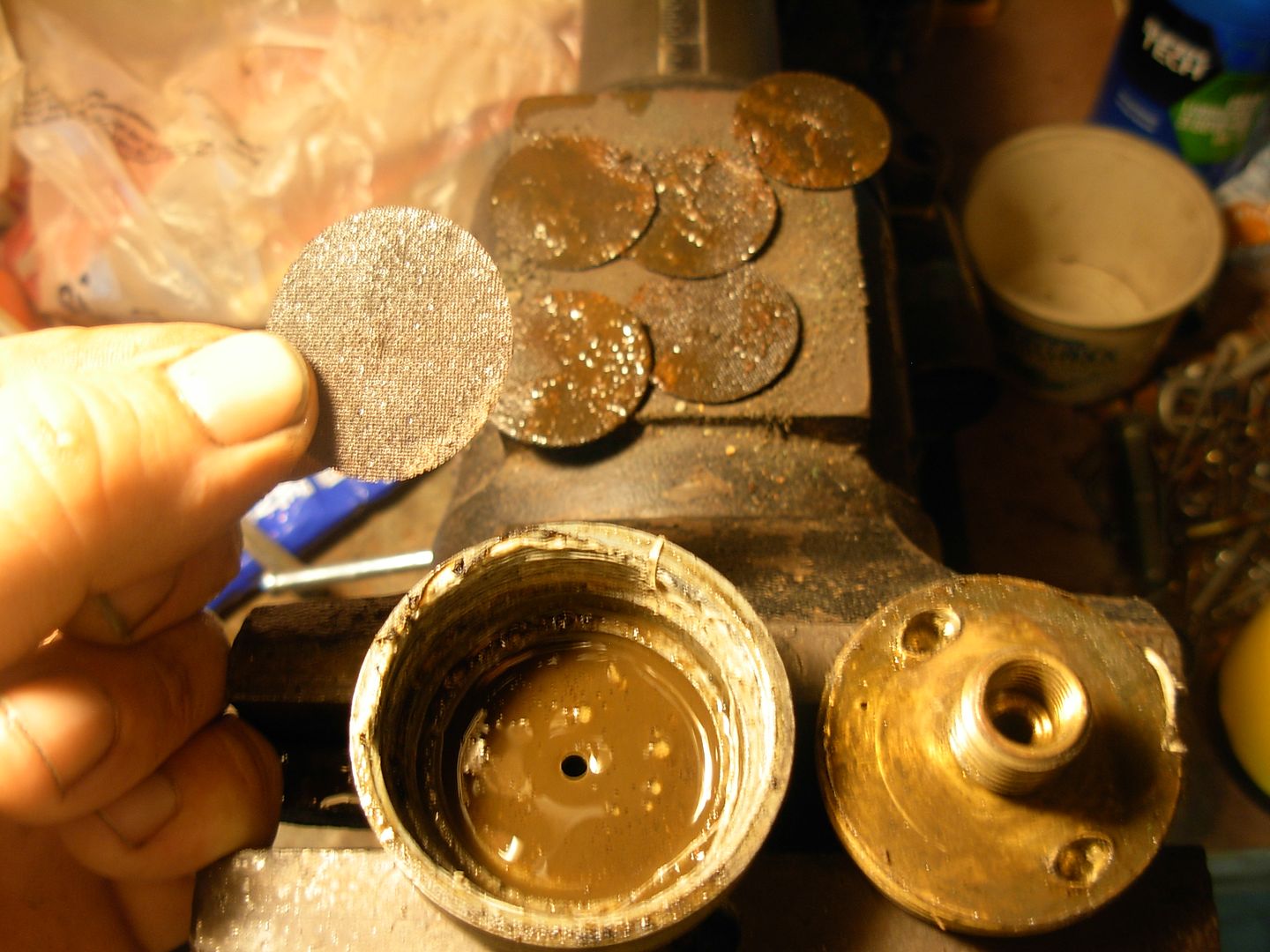
-From regulator through screen filter.
-From filter to manifold that splits the supply into 3 lines.
-1 line provides oil to the flat table way. The other two provide oil to the tables vee way (one on each side of the vee)

This is where the physical lines end.

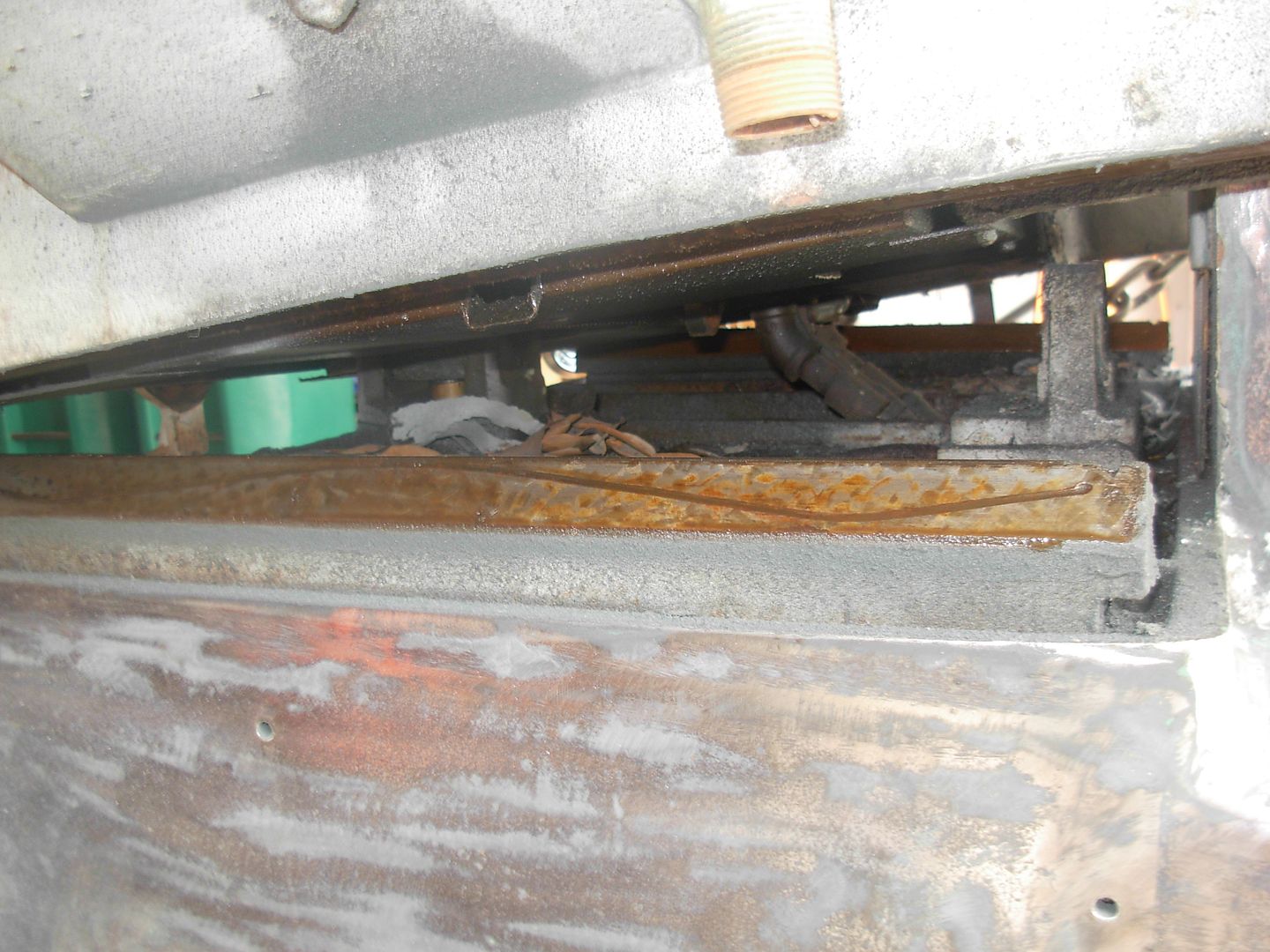
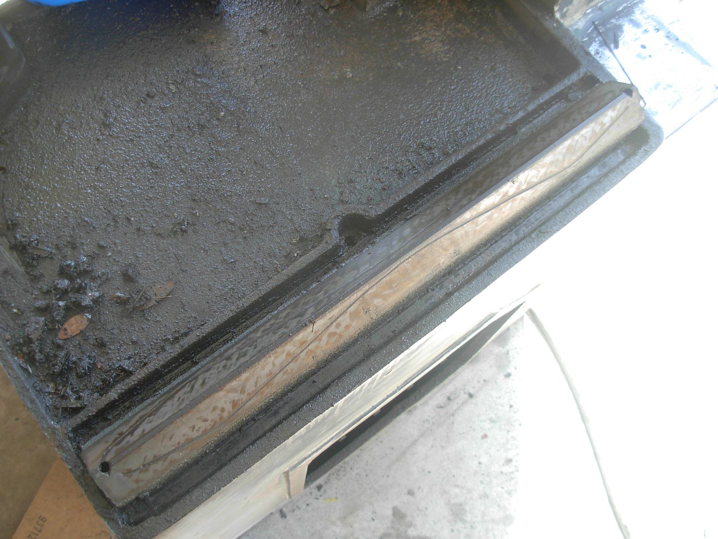
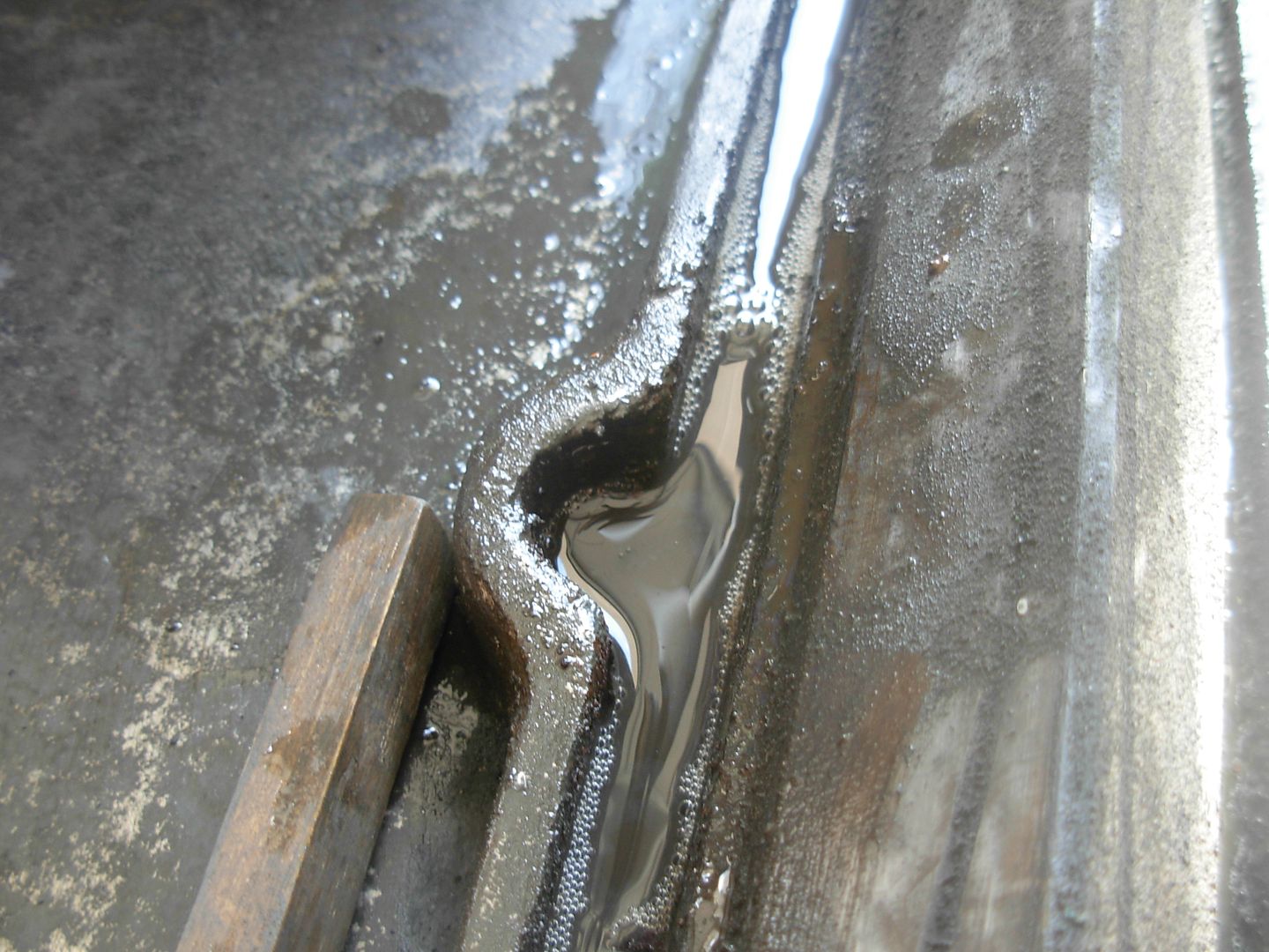
From there the excess oil from the table ways follows the oil channels on the sides of the flat way and the bottom of the vee way and goes to the left and right ends of the saddle where it collects in depressions.

There is a hole in each depression that allows the oil to drain through the saddle casting and end up right in the center of the saddle ways.

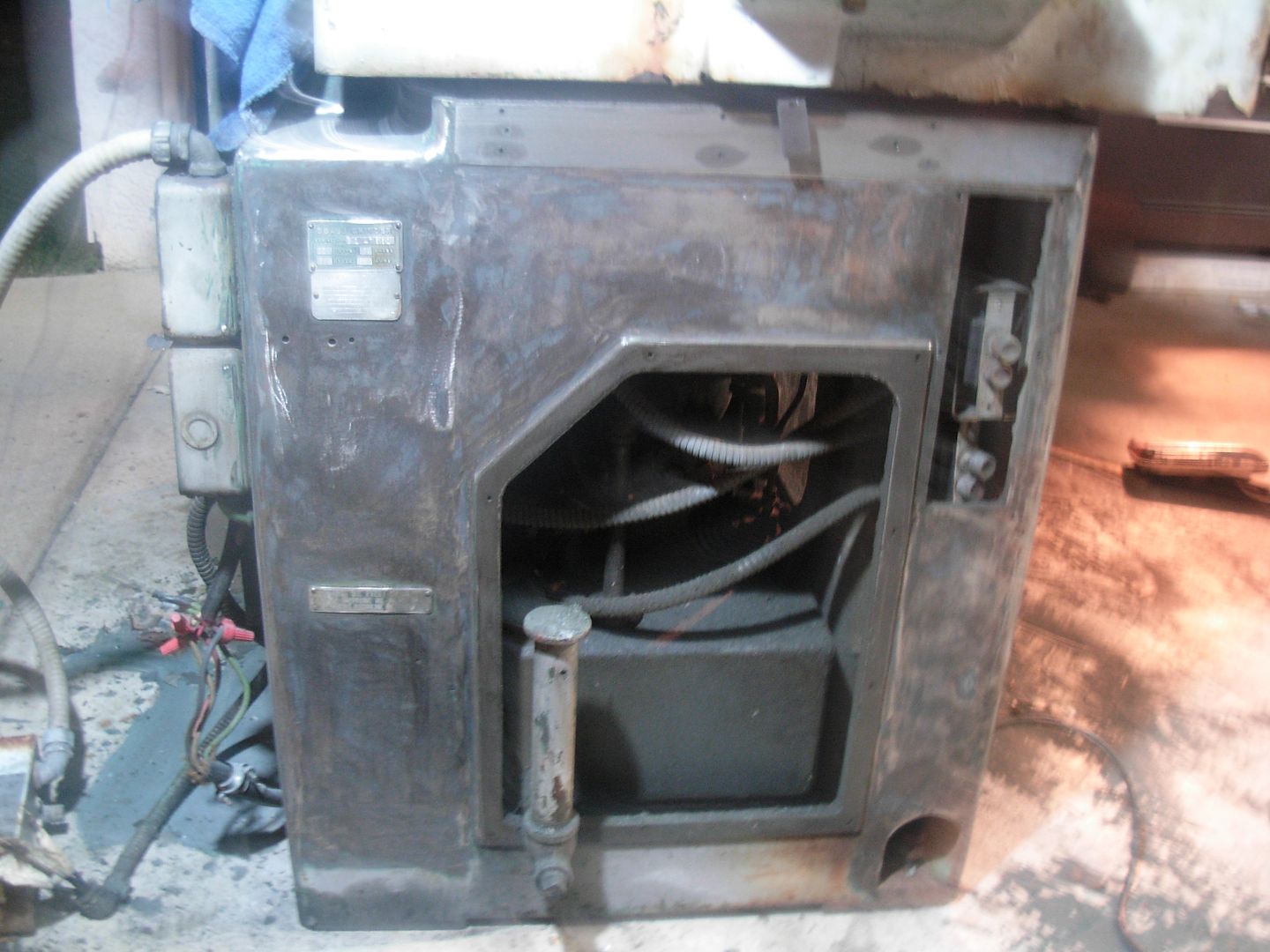
Excess run off from the saddle ways follows the oil channels cast around the ways on the cabinet and drain into the return lines that lead to the glass bowl filter which drains back into the tank to complete the oils travel through the system.


I've already cleaned out the entire oil path except for inside the combination valve ( which will only be flushed with clean oil once reassembled ) and the oil channels that go through the casting from the depressions to the saddle ways.

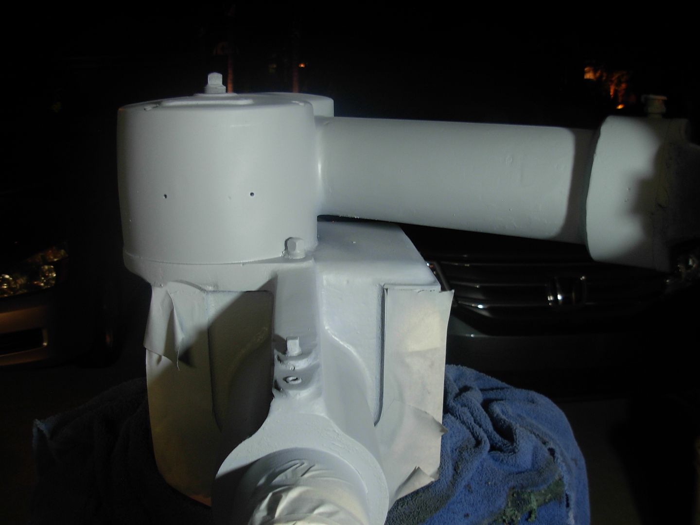
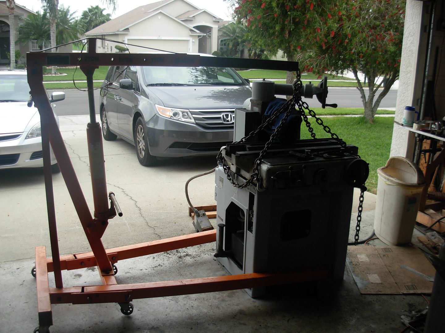
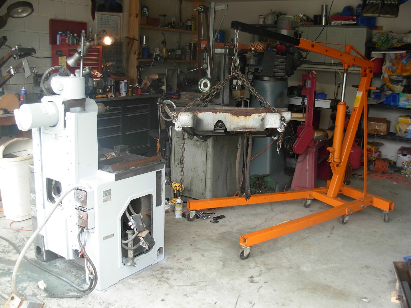
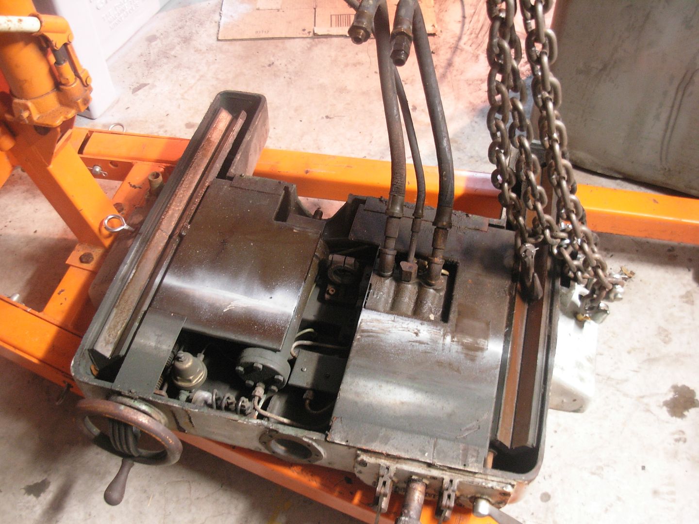
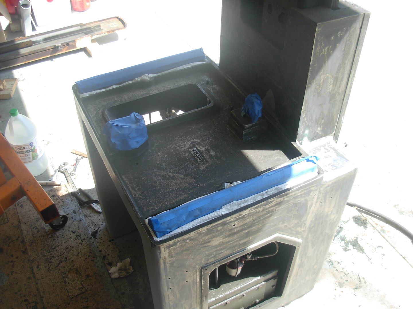
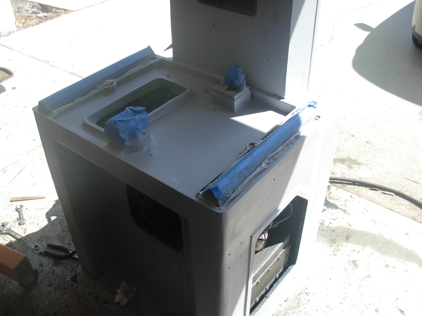
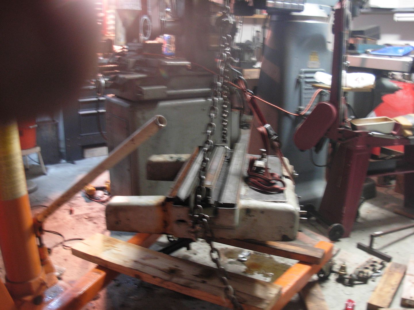
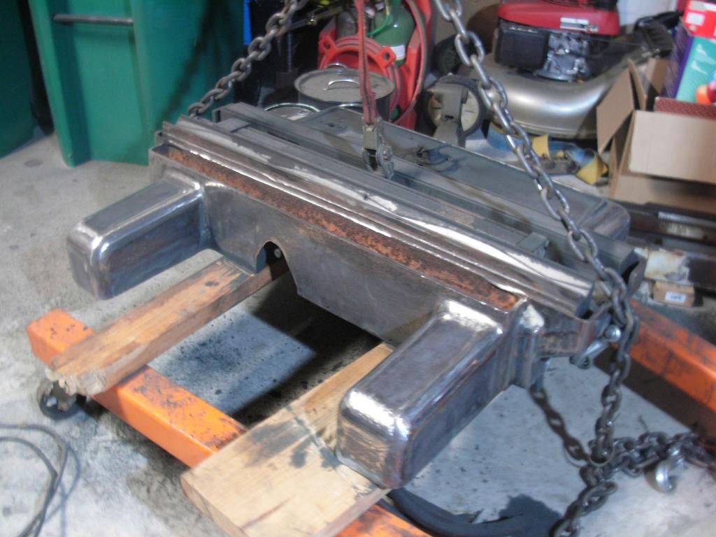
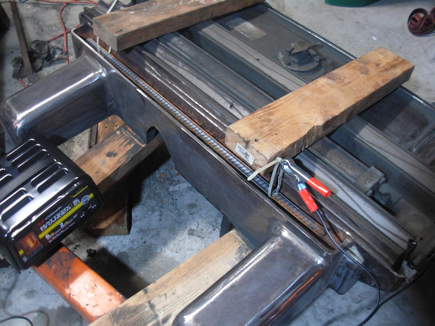
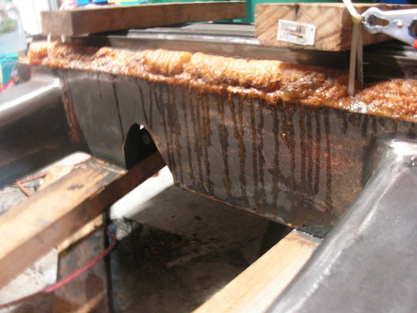
To clean thes channels and be absolutely sure the oil path is unobstructed I wanted to reposition the saddle on my hoist to get it relatively level and in the air so I'd have access to the top and bottom sides.

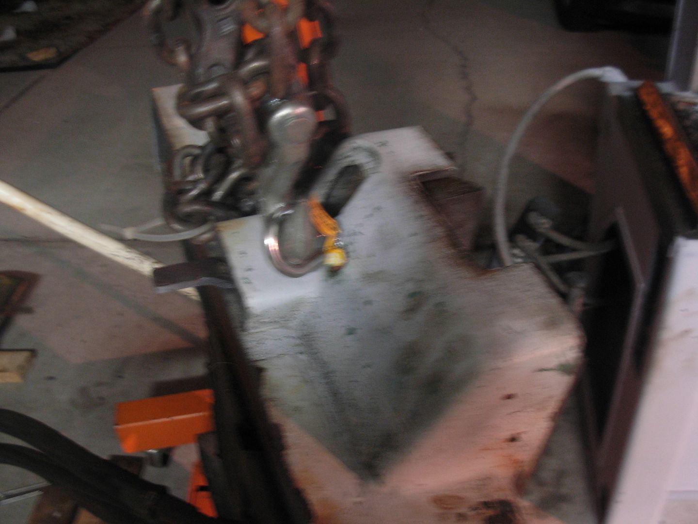
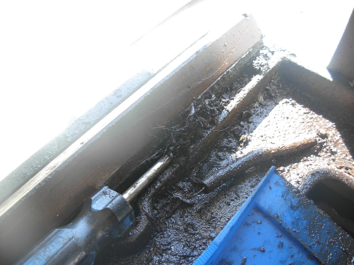
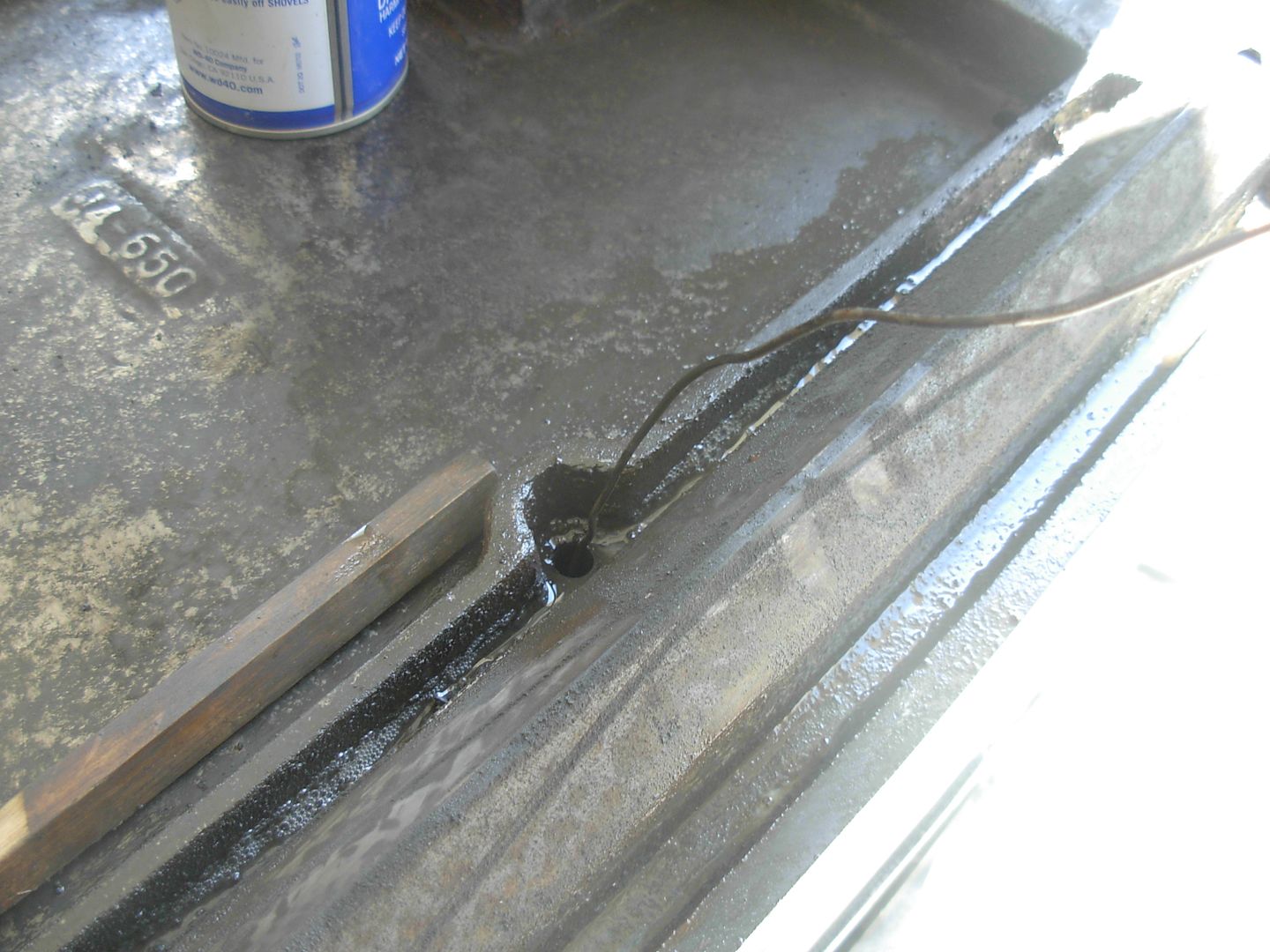
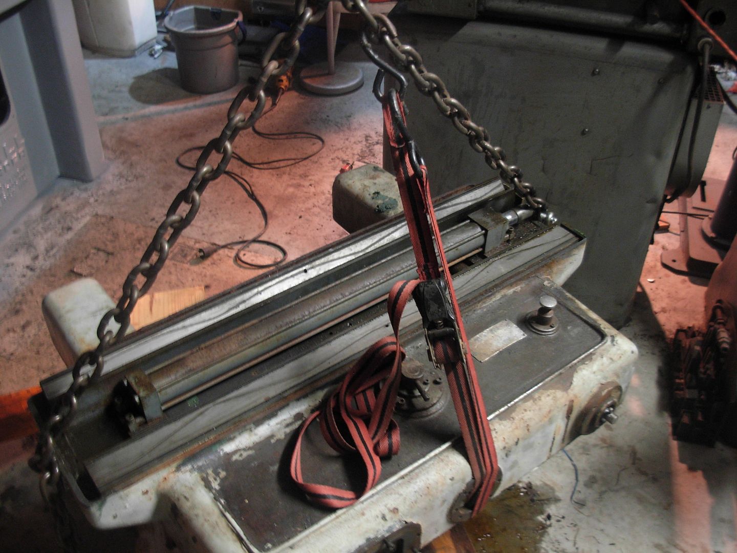
I'm no professional rigger but this is what I did which worked out really well. I set the saddle down and repositioned one hook so both my lifting hooks are the same number of links from the lift point. Then I added a ratched strap for a 3rd point to act as my load leveller.

001_zps0eb2aabf.jpg


Just ran the strap through the screw hole so tightening up the ratchet levels out the saddle front and back

002_zpse69c97a9.jpg


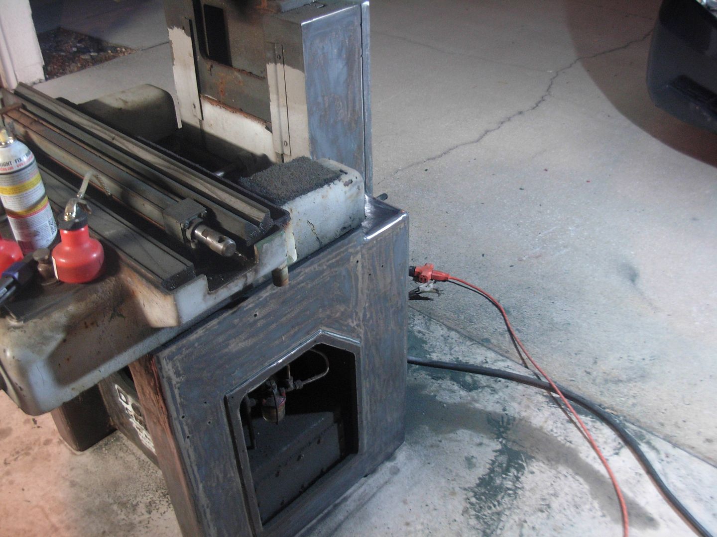
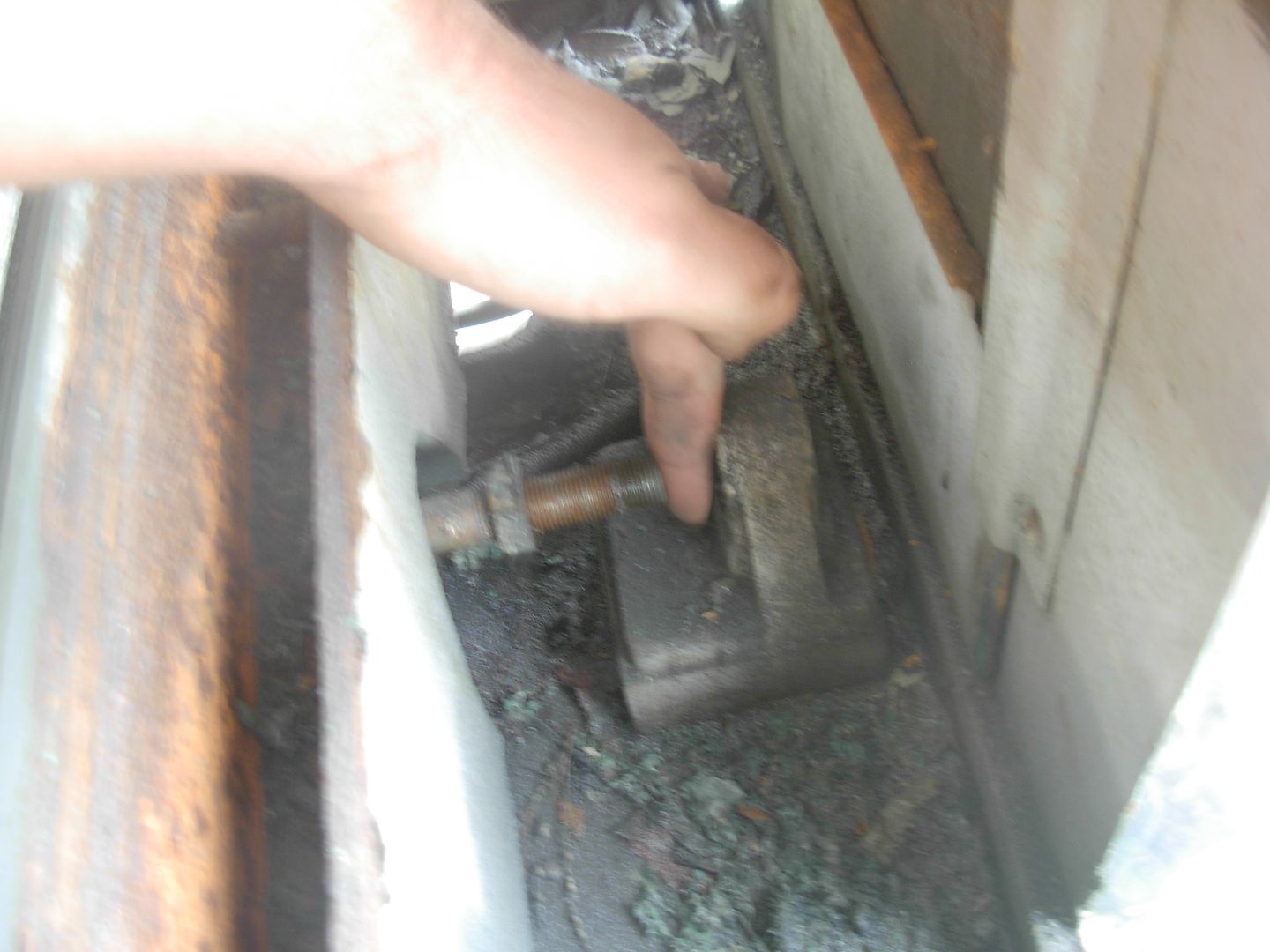
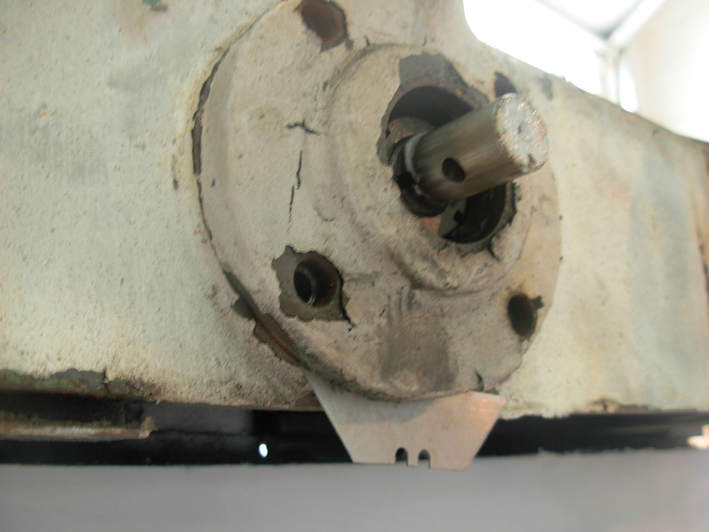
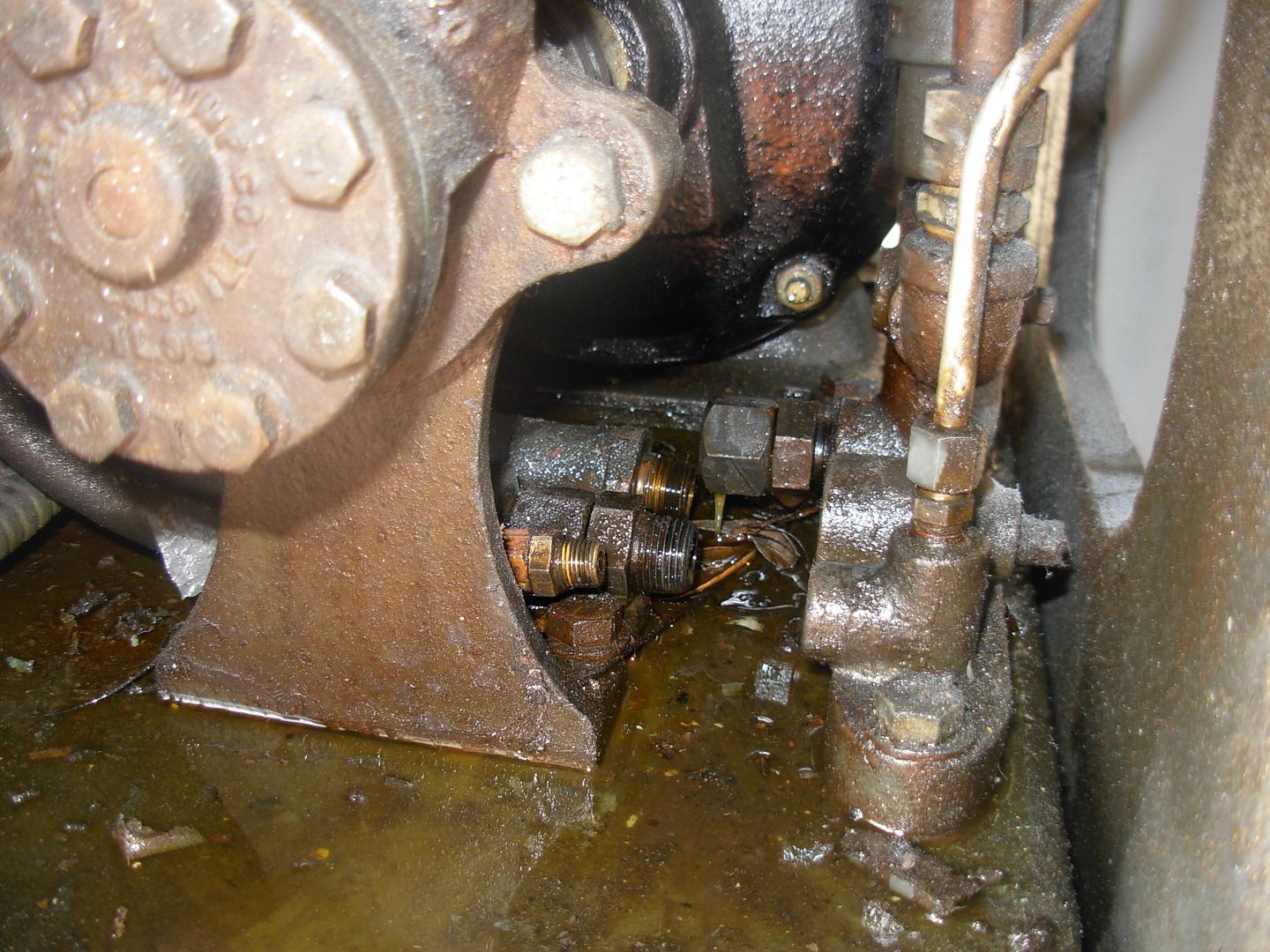
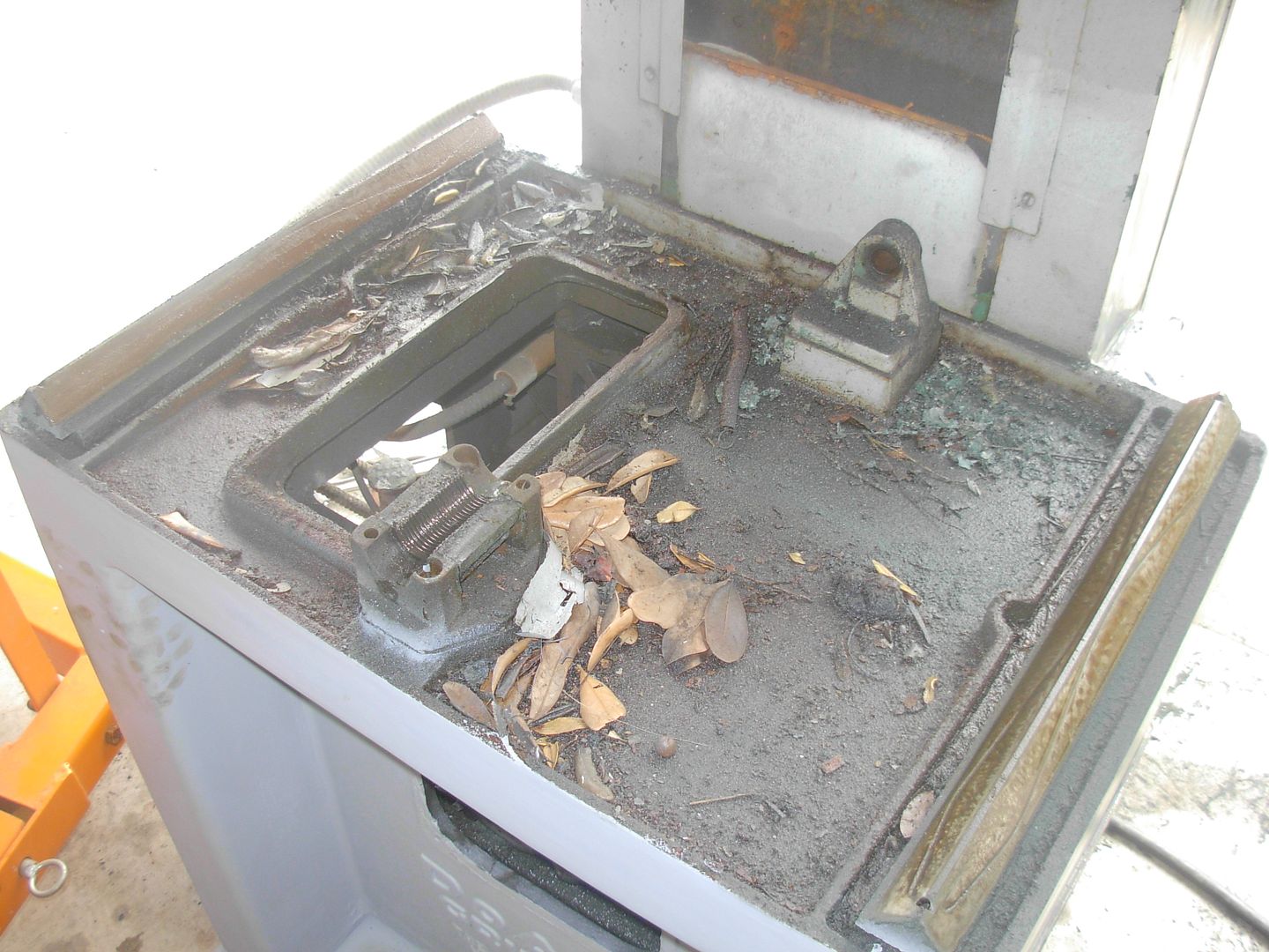
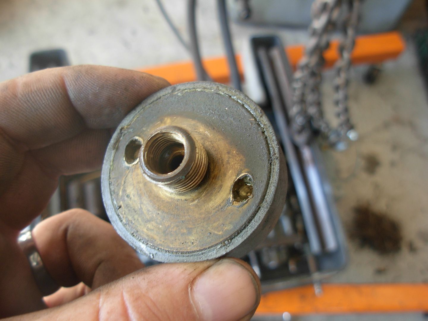
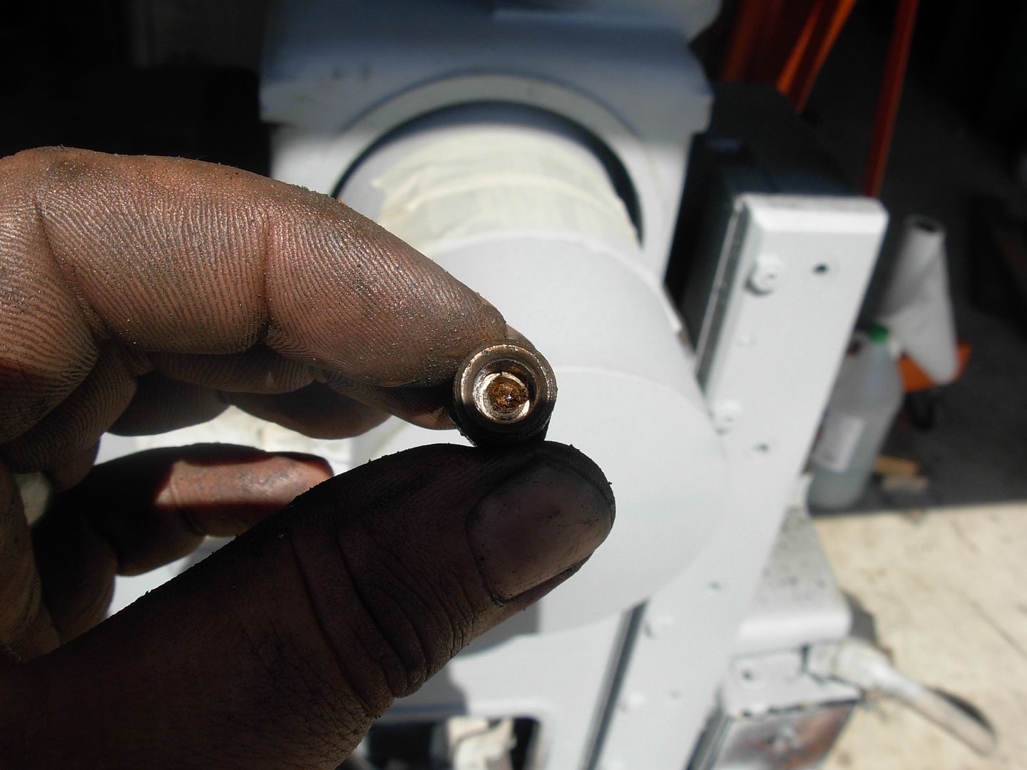
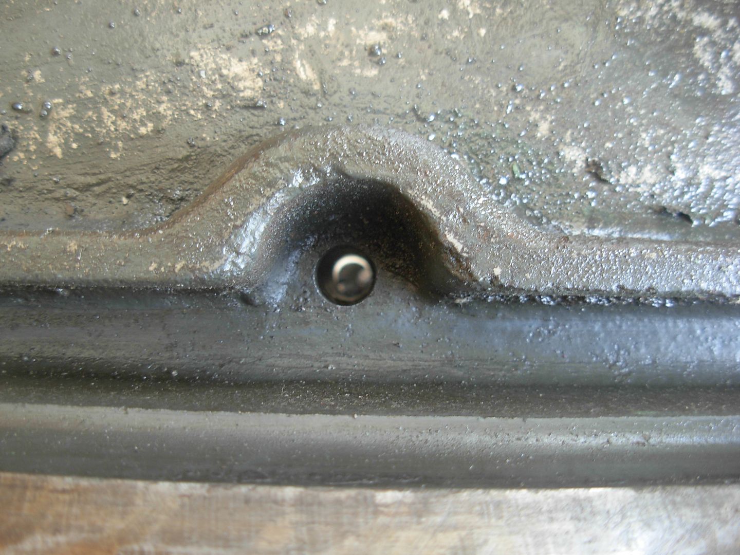
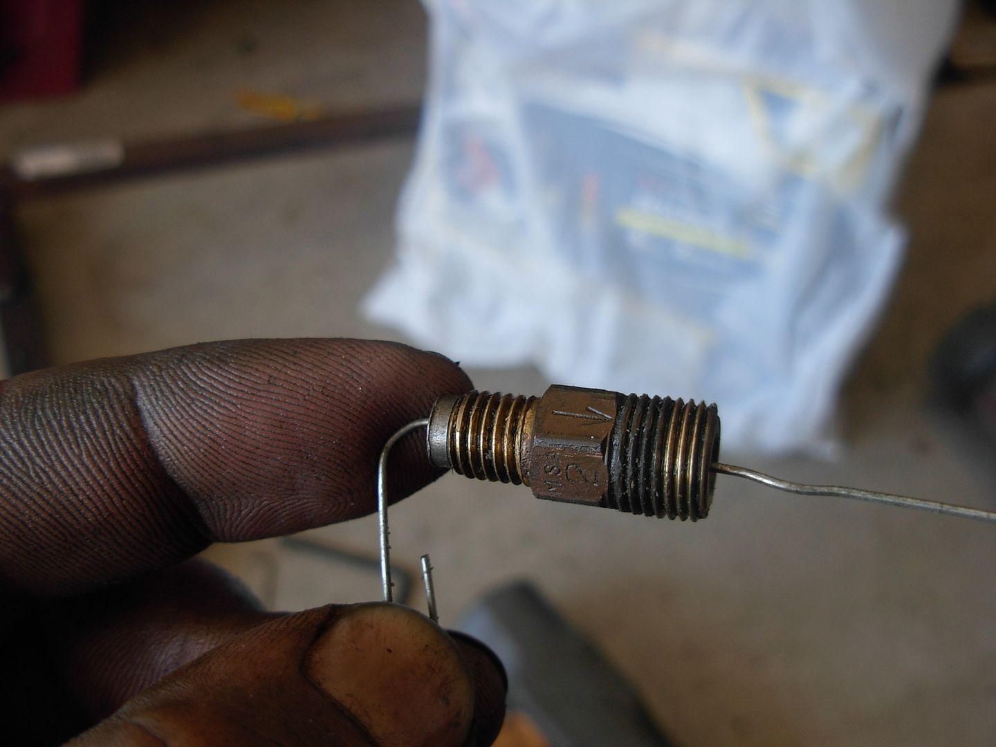
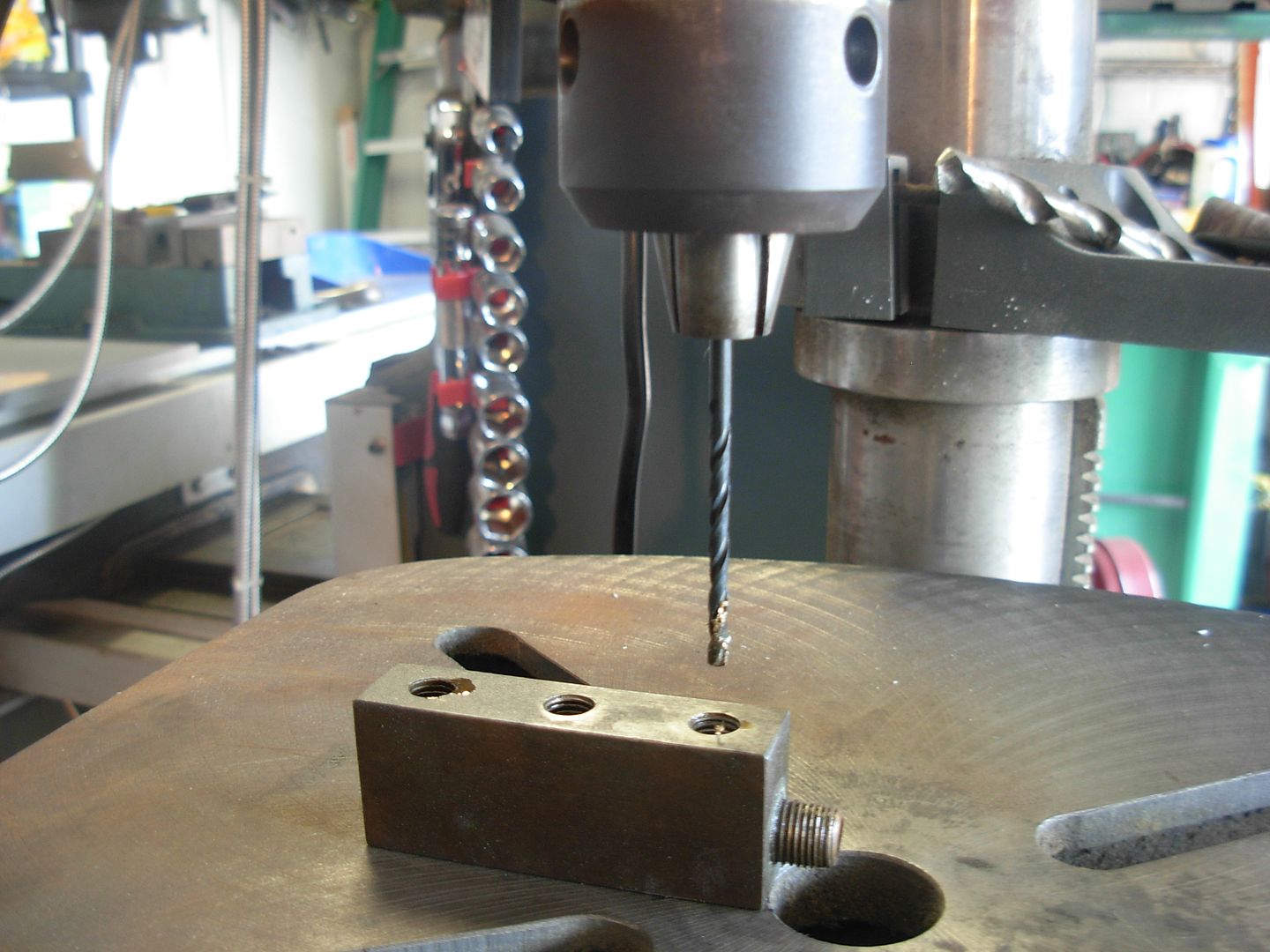
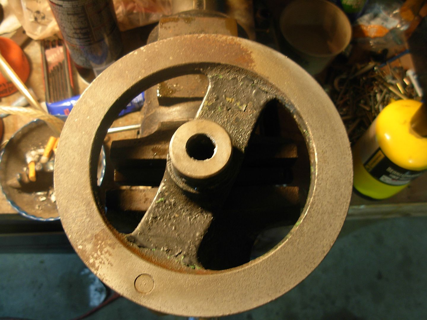
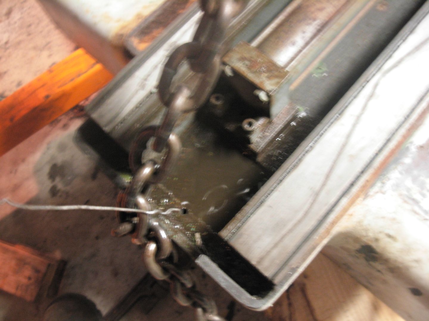
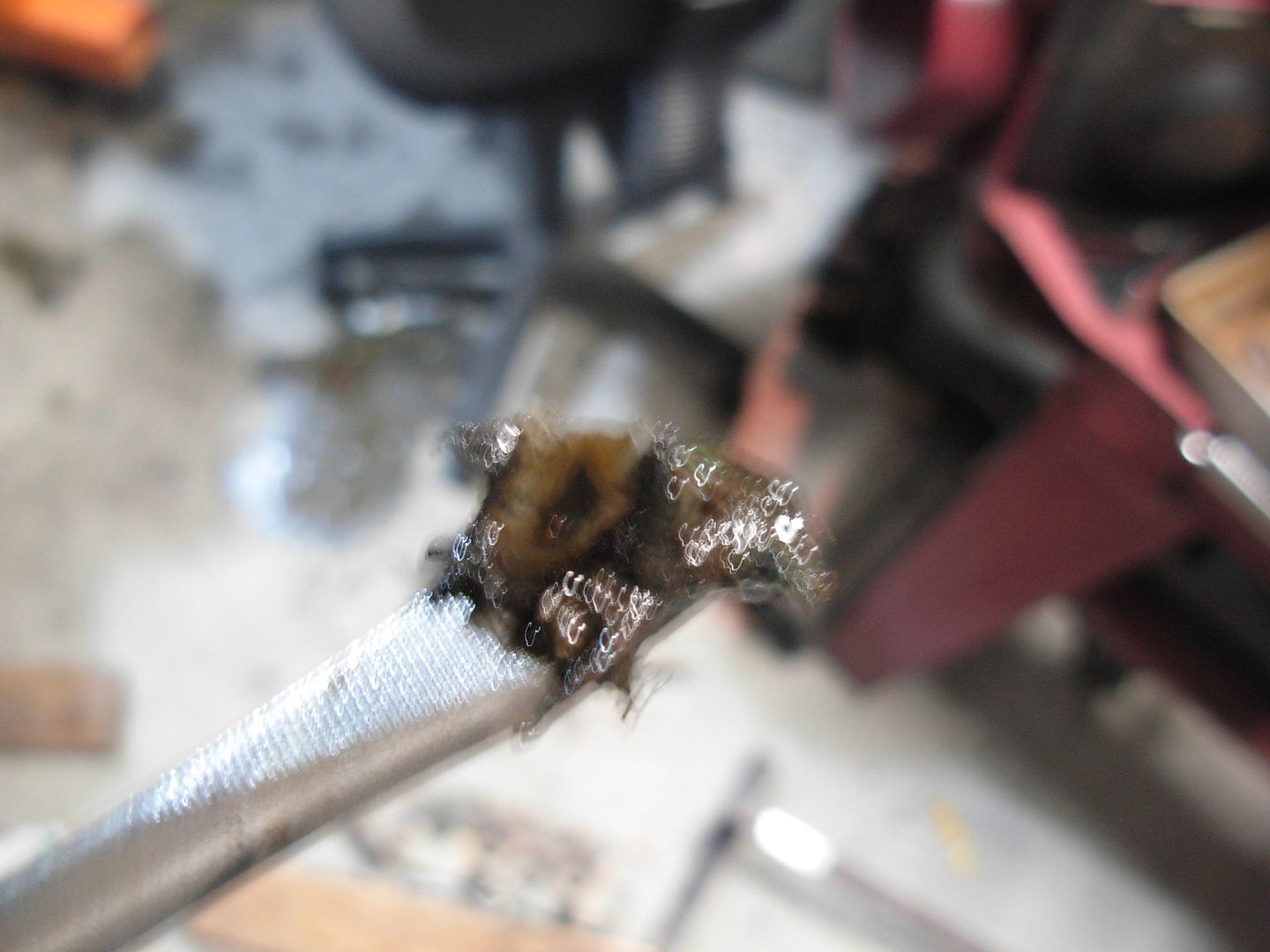
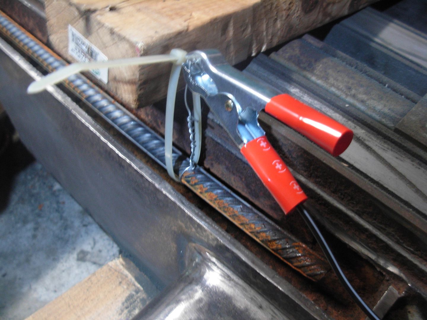
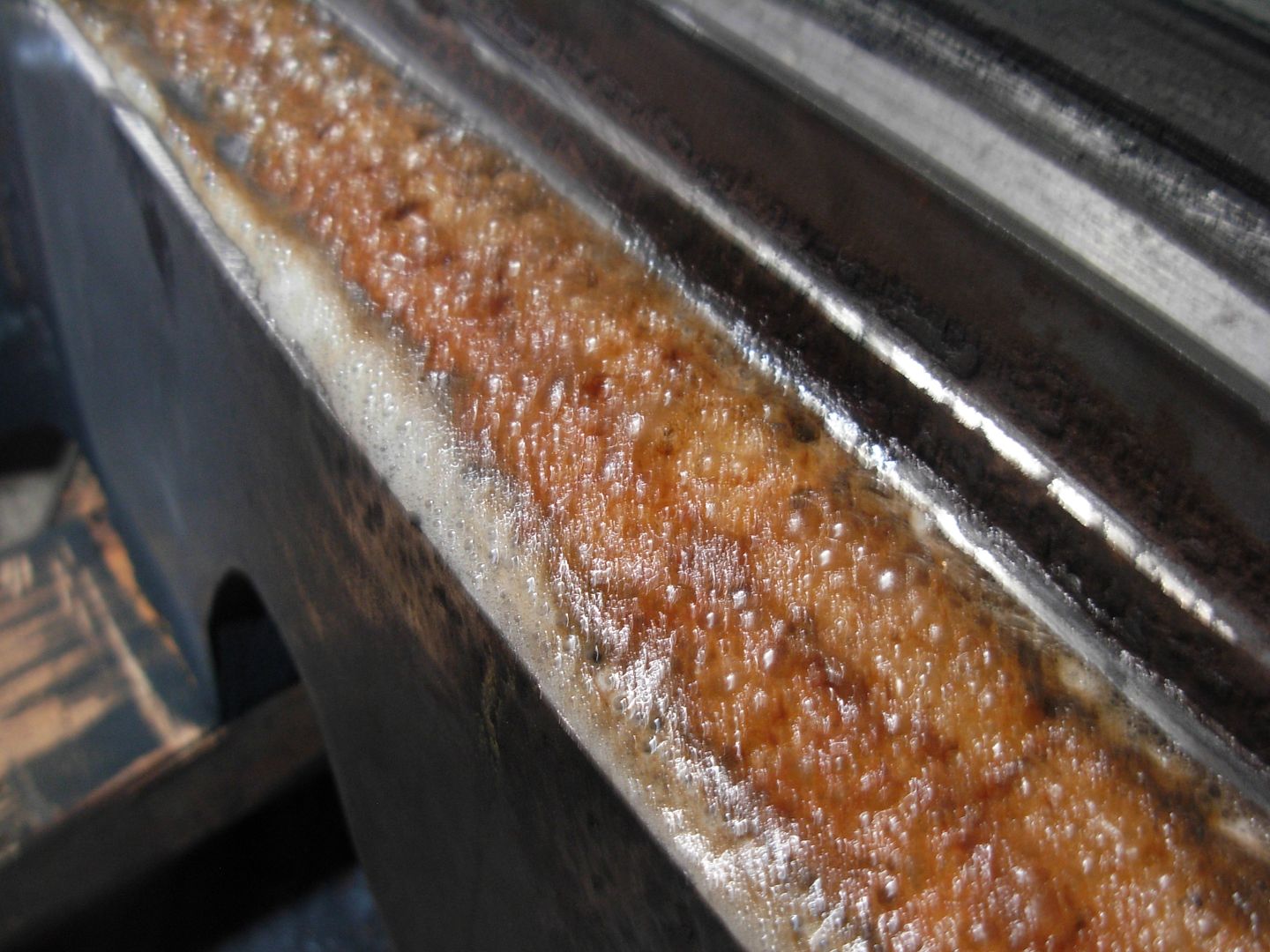
The wire is pointing at the depression hole that carries oil to the saddle ways. This side was clogged with loose paint and crud

003_zps803ac76b.jpg


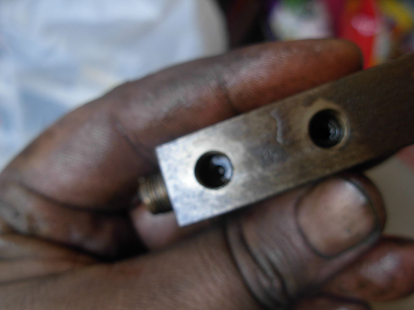
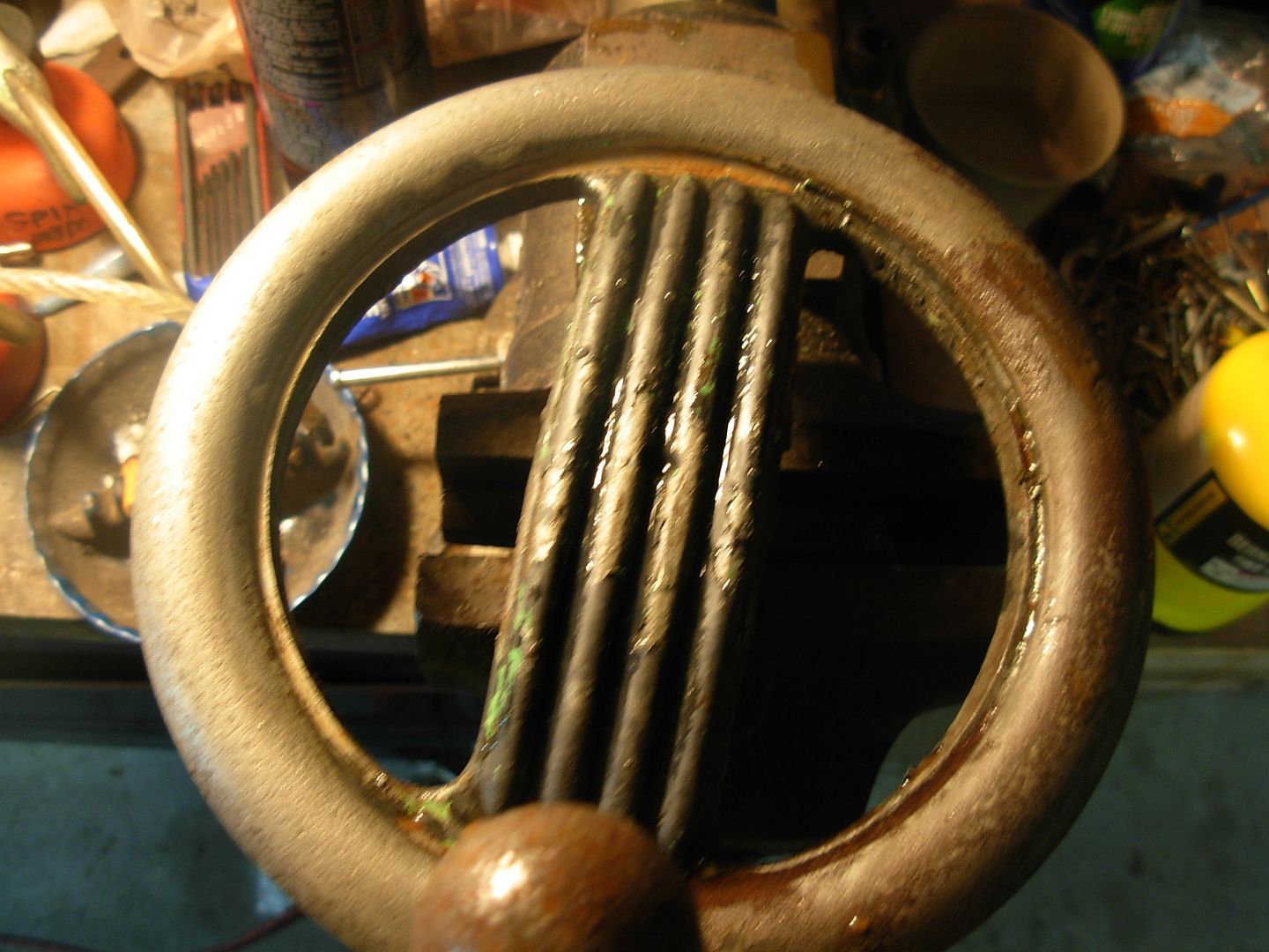
Here's the other side. All this grit will end up flushed right onto the saddle ways because there's no filter or anything between here and those ways. A thorough cleaning of these areas had been done :)

Now I know 100% that all my oil passages are clean from the comination valve all the way back to the tank !

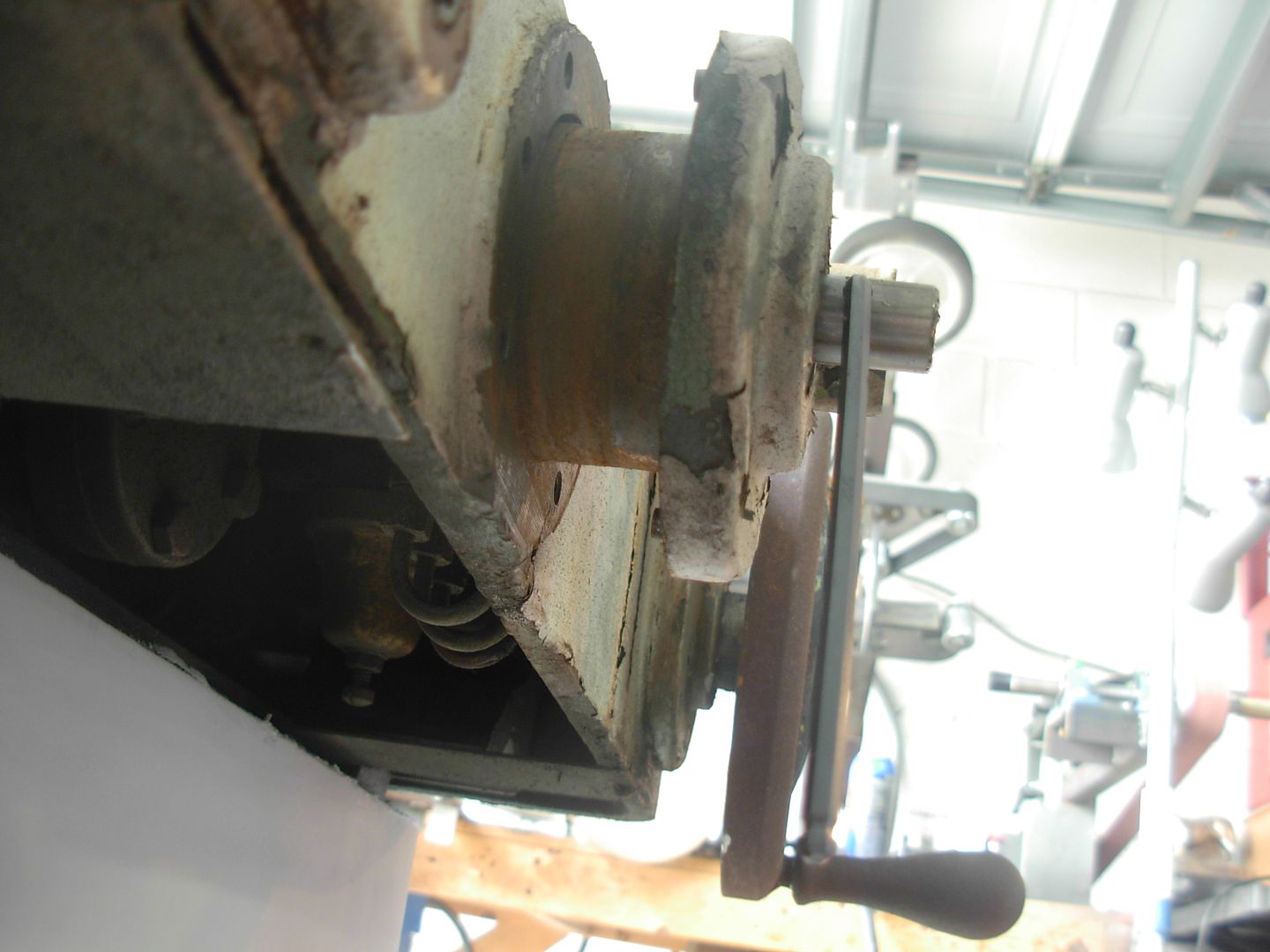
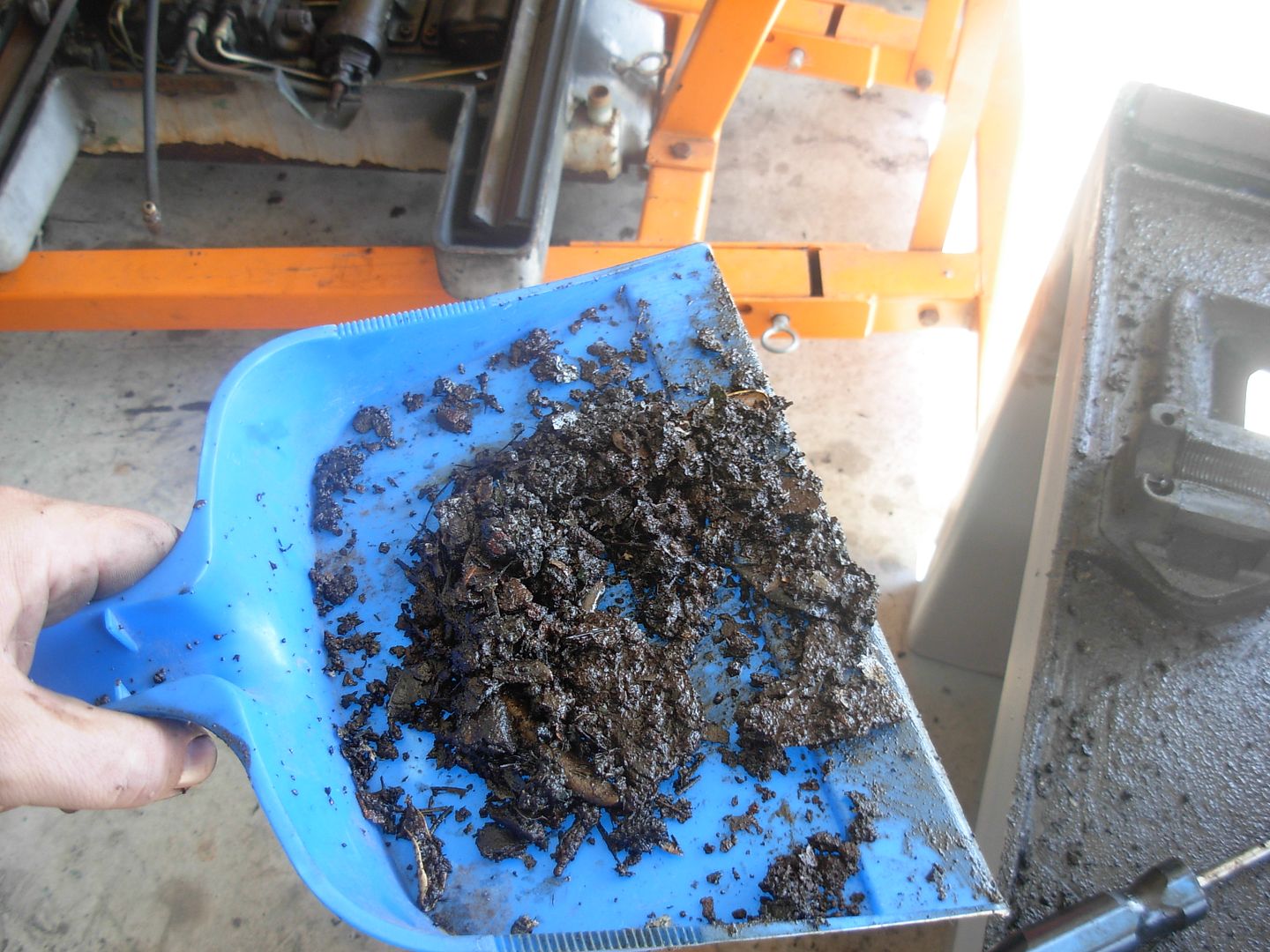
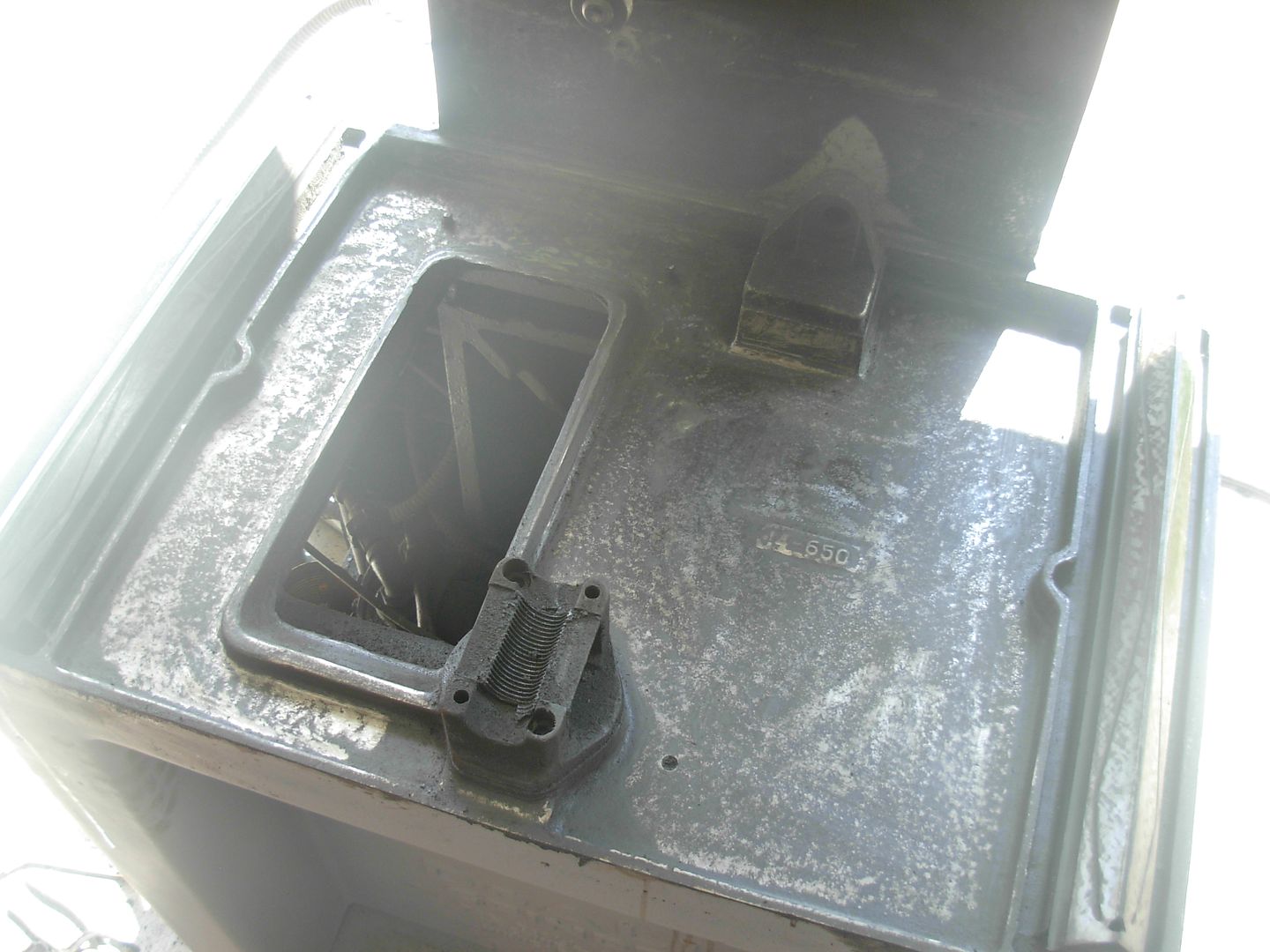
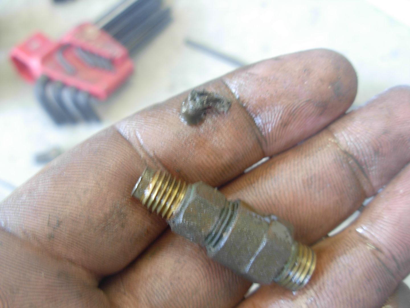
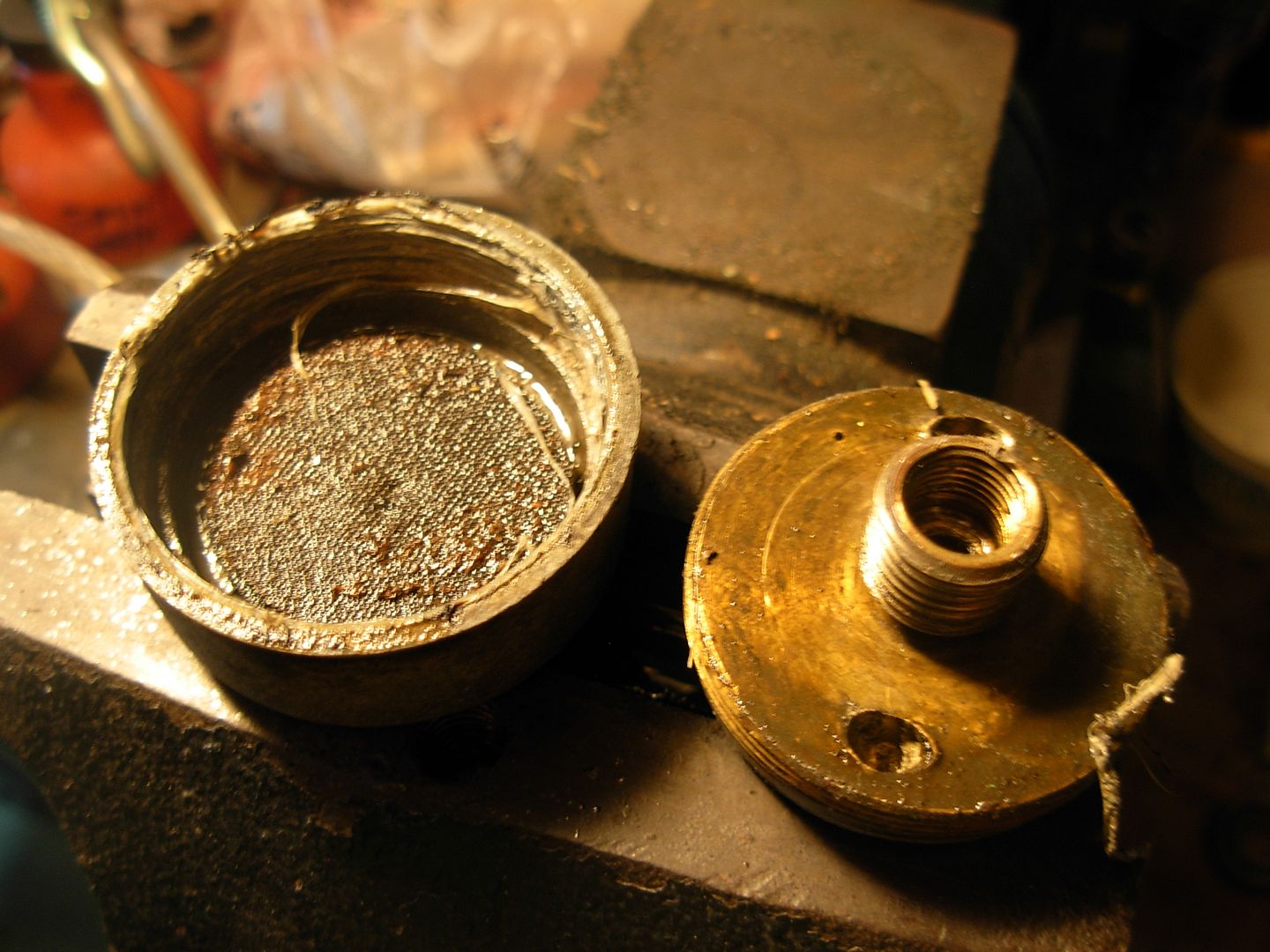
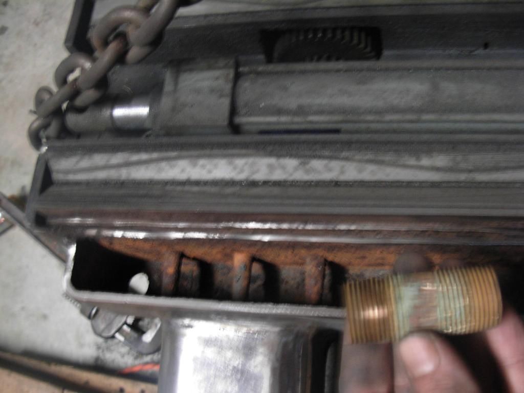
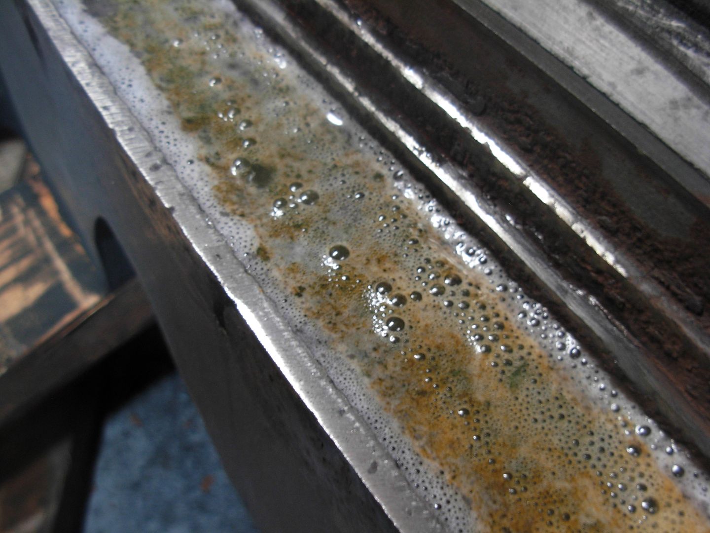
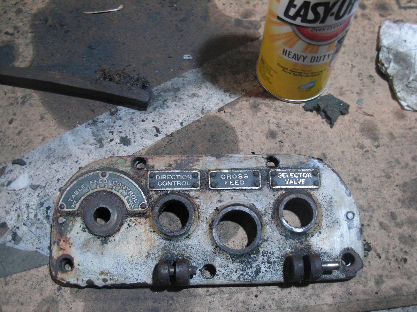
A bunch of paint and crud like this came out of those oil depressions. Only a matter of time before this gunk clogged up a passage starving the saddle ways of oil. I was curious about the bolts on the side of the saddle that I removed and installed the eye hooks in. Now it's obvious that these are clean-out ports for the oil passage so you do not have to remove the table to clean out a clogged passage.

005_zpscc040bdf.jpg


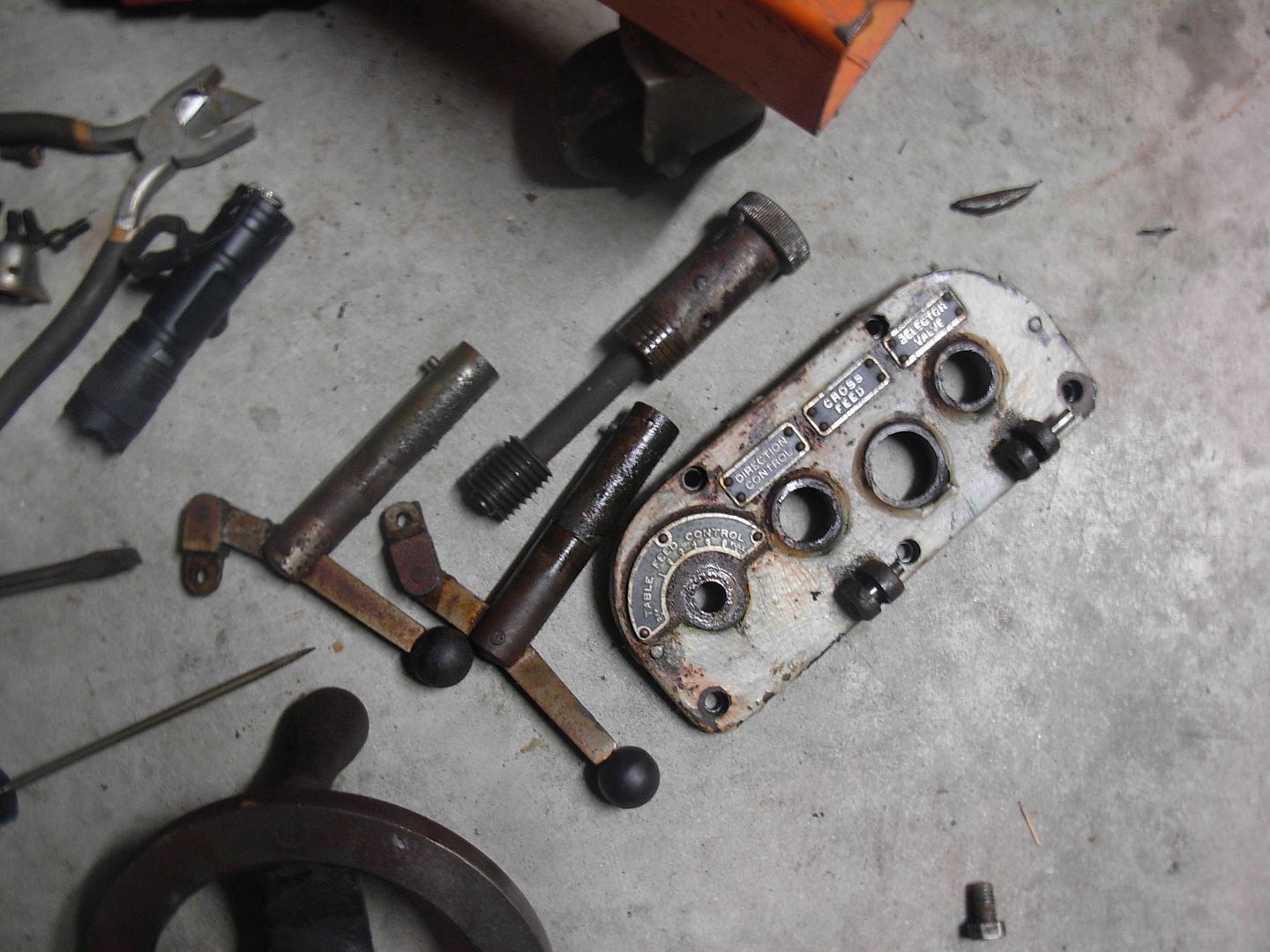
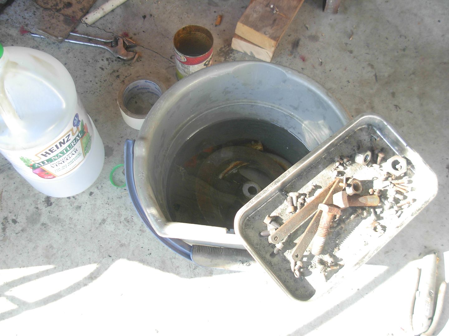
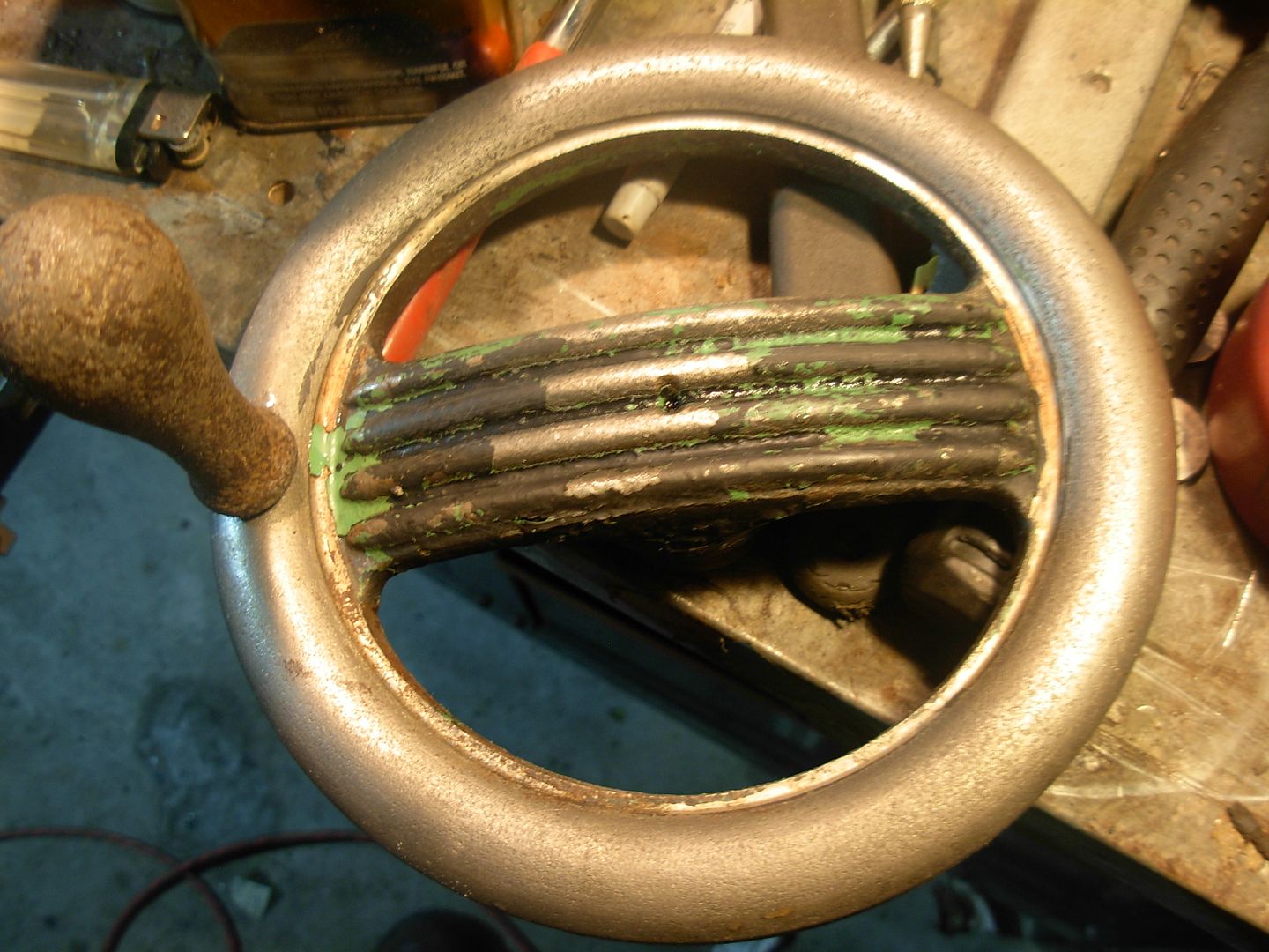
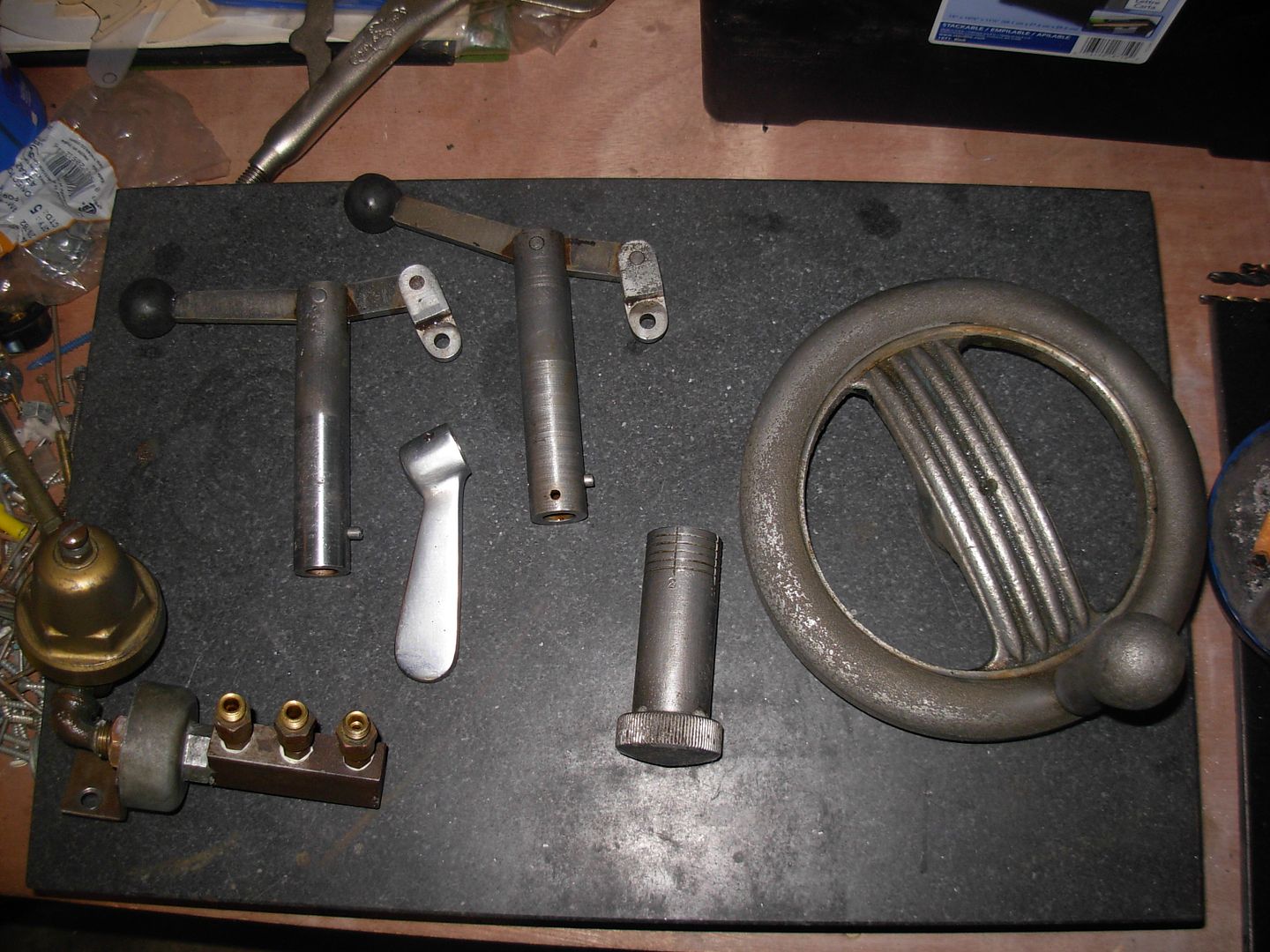
I spent the rest of the night wire brushing the parts in my vinegar soak. All looking good but I dropped them back in to looses some paint that's still on the center of the handwheels and the control levers and knob.

I did some running around this morning though and got some more oven cleaner so I should be able to strip that paint pretty easy now. Also got more paint, primer, and some thread sealant for reassembling my hydraulic lines and two replacement springs that retract the dist cover that keeps grinding dust out of the cabinet.

I'll be moving forward with stripping and de-rusting the table, saddle, and all the dust shields, brackets etc.

Once all that is done reassemble the machine and tackle draining and cleaning out the tank and figure out a filter solution for the tank.

Still alot to do before she's running again !

-Josh
 
I took apart and reassembled my regulator/filter/manifold/meter using Thread Sealant so it's now ready to be bolted back in place under the saddle.

Finished that up and got busy stripping the saddle. I got about 95% of it stripped with it sitting on these boards so I'll just need to lift it up and strip the bottom edges where the boards are blocking access to my flap wheel.

001-26_zpsf1f08fe9.jpg


002-29_zps38a1163c.jpg


Here's a look down into the troff that runs along the back side of the saddle. This grinder originally had the option of a Cool Grinding feature that pumps coolant directly to the wheel. This troff collects the coolant for recycling through the system.

I've removed this copper pipe from the drain you can see on the left end of the troff. This is the worst rust on the machine as this copper nipple was plugged solid so the troff remained full of water while it was sitting outdoors for years.

To remove this rust inside the troff I'm going to attempt to use the electrolysis in a reverse fashion from what is typically done.

Instead of submurging my entire saddle in the elecrolite I'm going to fill the troff with the electrolite and submurge my anode into the electrolite. Should work but we'll know for sure soon enough.

This is my first experience with the process of Electrolysis Rust Removal so please do your research if you want to try it out ! Goggle or Youtube search for "Electrolysis Rust Removal" and you'll find tons of info.

This process is for use on steel and iron ONLY. NOT stainless or other metals as toxic gasses will form. Because of this fact I picked up a black iron nipple and cap to replace the copper with.

Also burned up my flap wheel and picked up another. Boy did I get my moneys worth outta that flap wheel !

If you happen to be a Forger you're probably thinking the same thing I am.... Could electrolysis be the ULTIMATE scale remover.... Hmmmm. Before I'm done here we'll know for sure.

003-27_zps456afeef.jpg


-Josh
 
Time to get our electrolysis on !

I've got everything set up here.

Rebar is the anode and suspended in the troff WITHOUT touching the saddle anywhere. It's just hanging with some zip ties but I've got some steel wire wrapped tightly around the rebar and wrapped around the hangin nail to make my electrical connection to the positive charger clip.

Negative charger clip is clipped directly to the saddle close to the troff area.

I'm ready to go here just need to fill the troff with electrolite and plug the charger in.

001_zpsda407ff2.jpg


A closer view of the same

002_zps10070535.jpg


The electrolite is just a tablespoon of Washing Soda per gallon of water. I got the washing soda from Walmart in the section with the laundry detergent. A few bucks for this large box so it's dang near free.

003_zpsfa2db68c.jpg


Fill'er up and plug in. The bubbling action begins immediately if everything is connected correctly. This is approximately 1 minute after plugging the charger in

004_zps70c1ba1c.jpg


After a few more minutes it's building up a nice head of rusty foam.

005_zpsde3d82ba.jpg


I picked up this charger from Tractor Supply Company for $30. It has 3 different settings so of course I started out with the highest setting of 12Volts 6Amps. At this setting the charger would run for a minute or so and trip it's internal circuit breaker. Notice the charging meter is at zero...

006_zpsaaeab909.jpg


A couple minutes later and it kicks back on all by itself. I'm figuring this can't be a good thing so I switched it to the 12Volt 2Amp setting which solved this issue completely.

007_zpsd60799c9.jpg


While I'm fooling with this I'm also stripping this bracket for the controls. I don't want to lose the paint from the labels so I'm going at it by hand with the oven cleaner

008_zps807474d4.jpg


I filled the troff to the rim with electrolite so there's no space to contain the foamy mess. I don't think a little runover is going to hurt anything but I did de-foam it multiple times.

009_zpsc5363a4f.jpg


Also started getting my parts out of the vinegar soak and cleaning them up. Wire brush, degrease with Mean Green, spray down with Ballistol to prevent flash rust from forming. Ran out of time to finish but I got most of it

010_zps02089fe6.jpg


I left the charger running over night on the 12v 2a setting. With time the charging meter is getting lower and lower and the foaming action isn't much now. Purely speculation but I'm guessing the annode is getting so rusty it's passing less electricity through it or perhaps the tiny wire making the annode connection is rusing out. Later I'll drain this sucker and see what I've got then decide whether to run it some more or clean it out and shoot it with primer.

Pretty cool stuff :biggrin:

-Josh
 
Back
Top