RickA
Well-Known Member
Hi everyone
As mentioned in my 1st knife posting I am currently busy building a KMG grinder.
I have read quite a lot about various grinder designs in the past couple of months, and while I really like the EERF grinder design (http://blindhogg.com/eerfgrinder.html), with the motor mounted directly on the frame, ideally this seems to require a 3Phase motor and VFD which I don't have.
I will be using a 220V single phase, 1.1KW(1.5HP) pool pump motor, which runs at 2850rpm, so I will need to use step pulleys for variable speeds and the KMG design looks better suited to accomodate the step pulleys.
I wasn't able to find some of the steel sizes listed in the KMG design tutorial I got off BritishBlades (http://www.britishblades.com/forums/showthread.php?60352-Let’s-make-a-Grinder) so have adapted the sizes slightly, for instance I could not find the 35x35mm square bar in bright mild steel, so opted for 38.2x38.2mm square Aluminium bar.
I changed parts of the design to accomodate building the grinder using drilling and tapping rather than welding. I have used Michael Clerc's design for some of these mods (http://www.scribd.com/doc/24148558/Grinder-Plans)
I have also had to make some tools to accomodate the drilling/tapping operation. I could not find a tool supplier locally in South Africa who knew what a transfer punch was? so I ended up making my own out of old drill bit shanks, ground to a very shallow point, and they have worked brilliantly in aligning holes to be drilled.
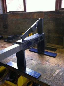
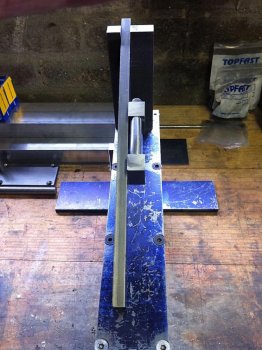
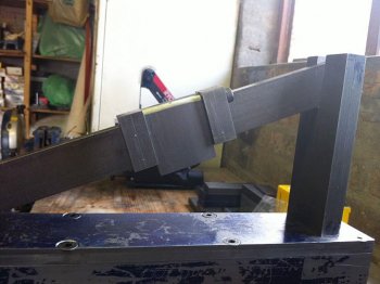
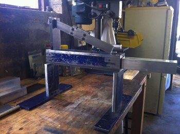
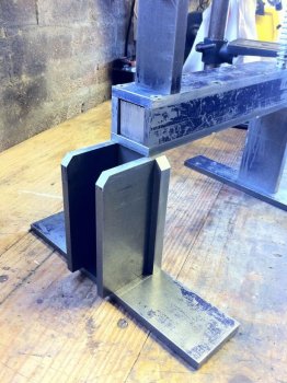
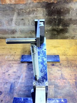
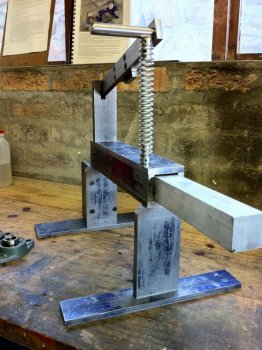
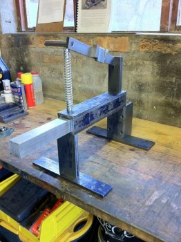
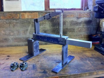
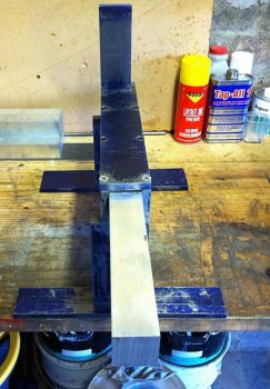
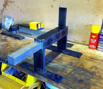
So far I have built the toolarm box, with it's support legs and feet, and have added the tracking arm support post.(still to be cut / fitted for the tracking arm). The next part will be to add the rear bearing mounts for the drive wheel drive shaft / step pulleys, although I will have to make a plan to have these drilled as my current drill press has a max drilling diameter of 10mm in steel, and the drive shaft bearings require a 20mm drive shaft.
I also need to reduce the height of the toolarm box sides by +/- 0.8mm as the vertical play in the toolarm due to the difference in steel size (40mm) vs Alu (38.2mm) appears to be too much (1.8mm). What sort of gap is acceptable here? There will be a tool arm clamp threaded in from the side of the toolarm box? but will this clamp be enough to make up for the large gap?
I also still have to come up with drive wheels, contact wheels etc - I have looked at the possibility of using castor wheels, with decent bearings fitted, however have heard some stories about knife blanks being badly ground due to imbalanced contact wheels so I may just bite the bullet and buy some decent contact wheels (very expensive here in South Africa).
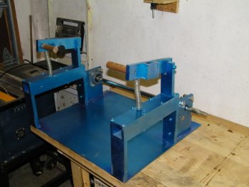
See below for a couple of photos of the grinder build so far!
Thanks
Rick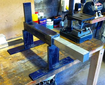


