Knifemakers Vise-Tutorial

Mike Barton

Well-Known Member
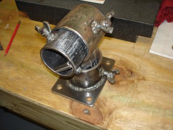
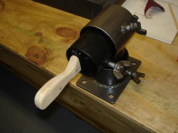
After seeing a few other makers use different versions of a Knifemakers Vise, I decided to fabricate my own from the best example I could find. I joined the Knifedogs forum and shortly after Tracy posted the new Knifemakers Vises he was adding to his US Knifemaker online store, I knew I had found my inspiration. After a asking few questions, Tracy was most generous to answer, I fabricated a working Knifemakers vise.

Tracy wanted me to post a picture of the vise when finished and I went overboard and took pictures throughout the build. I wish to thank Tracy for his generosity in letting me post this tutorial on building my clone of his Knifemakers Vise on this forum.

Tracy urock1

A quick note on safety, be certain to wear the correct personal protective equipment for whatever equipment and materials you will be working with. Welding needs to be done in a well ventilated area, and any metal that is plated should be stripped bare if possible before welding it. Always wear your eye and hearing protection, your loved ones and friends will thank you for it. ;)

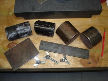
I built this using mostly scrap metal left over from other various projects as I wanted to keep the cost down. I did purchase new hardware and paint from the local home supply warehouse, and the neoprene rubber for the jaw inserts came from an online source.
Here's the list of materials I used:

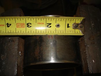
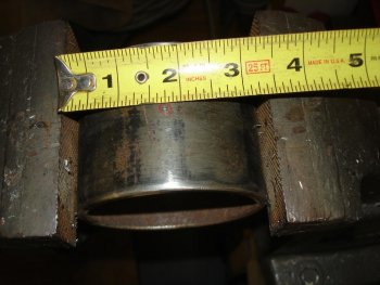
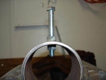
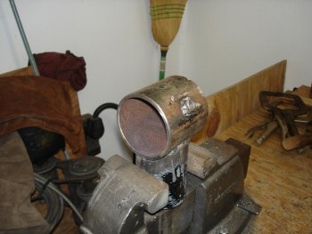
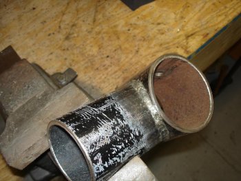
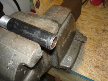
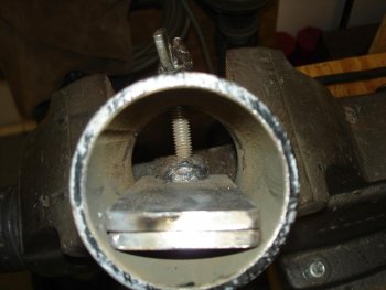
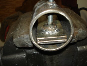
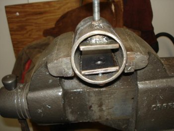
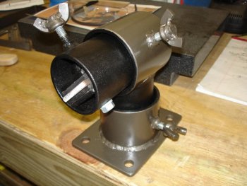
10 inches of 3" dia. steel pipe for the vise body and frame pivots(heavy wall)
6 inches of 3 1/2" steel pipe for the fixed frame portions(heavy wall)
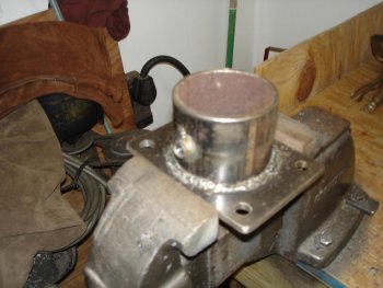
6" x 4 1/2" of 1/4" steel plate for the mounting base
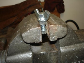
12 inches of 2" x 1/4" steel plate for the vise jaws
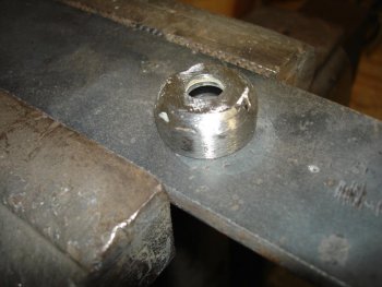
3/8" long piece of 1" steel pipe for the upper jaw position bolt retainer
Two 3/8" flat washers to cap the 1" pipe
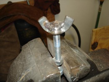
One 2 1/2" x 3/8" NC bolt for upper jaw position
Two 5/16" washers to attach to the end of the upper jaw positioner bolt
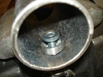
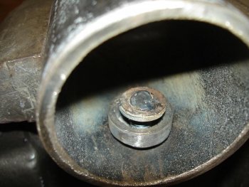
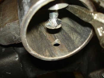
One 1 1/4" x 3/8"NC bolt for the bottom vise jaw
Two 1 1/2" x 3/8" NC bolts for vise rotation position
Three 7/16" wing nuts to make all bolt heads hand adjustable
12 inches of 2" x 3/16" 40 duro black neoprene rubber for vise jaw inserts
Rustoleum Bronze hammer finish & Black textured paint
 
Last edited:
The first thing to do is measure and cut the vise body parts
attachment.php


The base is already cut to size. Cut the 3 1/2" dia. pipe into two pieces, one piece 2 1/2" long leaving the other near 3 5/8" long. Cut the the 3" dia. pipe into two pieces, one piece 4" long leaving the other near 6" long. Cut the 2" flat stock to the match the longer length of the 3" diameter pipe. Be sure to dress all cut edges to help prevent leaks... blood is supposed to stay inside you :D

Next layout and center punch the metals for holes to be drilled. Both pieces of 3 1/2" dia. pipe will have the holes centered for their length. Divide the overall length of each piece and mark the center point, then center punch for drilling. Mark and center punch 1 1/2" from the end of the 6" long piece of 3" dia. pipe. Also mark the opposing inside wall at the same 1 1/2" distance for a reference when this piece is through drilled for the jaw installation. Measure 1 1/2" from the end and 1" from the edge of one of the 2" wide jaw plates and center punch for a hole.

Each corner of the base plate will be marked and center punched 5/8" in from each side for the corner mounting holes to be drilled. Find the center of this plate and place one of the 3 1/2" dia. pipes centered over the mark by eye. Measure from the pipe to all the edges of the plate adjusting until an equal distance is found for length and width and mark the outline of the pipe onto the base plate.

The 4" length of 3" dia pipe will need to be marked to cut out a saddle for the 3 1/2" dia. pipe to be welded into it as the upper rotational holder. One way to do this is to hold a piece of the 3 1/2" dia. pipe at 90 degrees over the end of the 3" dia. pipe without overlapping the end and mark along its outline onto the 3" dia. pipe below. Use a straight edge and mark the edges to the other side of the 3" dia. pipe and then use the same technique to mark the 3 1/2" pipe outline on this side. Unfortunately I did not get any pictures of this process as I was alone while doing this.

Now use your favorite means of rough cutting the semi-circles from both sides of the 4 inch long 3 1/2" dia. pipe. I used a hand held porta-band saw and slowly cut the steel away, it needs to be left a little undersized from your marked line. Your line may have been a little off the actual opening size needed. Use a grinder to slowly remove the excess steel near the line and match the opening to the 3" dia. pipe front and back. I used my 2" x 72" square wheel grinder with a 3" contact wheel, but you could use a hand held angle grinder and accomplish this. Just take your time and you can get it very close.
 

Attachments

  • 1 Pieces Layed Out.jpg
    1 Pieces Layed Out.jpg
    92.3 KB · Views: 873
Last edited:
[Next we drill the holes we marked in the base plate. Use a 1/2" drill and be sure to lubricate your drill bits. Be sure to chamfer all drilled holes, as it will keep the leaks to a minimum.
attachment.php
 

Attachments

  • 3 Lubricate Drill Bit.jpg
    3 Lubricate Drill Bit.jpg
    96.9 KB · Views: 793
Last edited:
Now we'll drill the holes in our pipe bodies for welding on the nuts that our locking bolts will need. First let's size the nut for a hole that allows a little room for placement error.
attachment.php


A 7/16" hole will leave a little wiggle room without allowing any weld spatter to get onto the bolt when the nut is welded into place.

I used a standard bench vise for drilling the holes in the pipe. Use a tape and center the punched mark from side to side.

attachment.php

attachment.php


Using a 7/16" drill bit, center the drill in the punched mark, be sure it is square and drill your holes.

attachment.php


The 6 inch long 3" dia. pipe will need to be drilled through both sides. Using the 7/16" drill bit, drill through the top of the pipe and align the drill bit on the mark made before on what is now the bottom of the pipe. Check your drill level to ensure you will be drilling as straight as possible and drill through the bottom of the pipe also.

attachment.php
 

Attachments

  • 4 Hole Sizing.jpg
    4 Hole Sizing.jpg
    79.4 KB · Views: 741
  • 6 Square Mark for Drilling.jpg
    6 Square Mark for Drilling.jpg
    90.6 KB · Views: 750
  • 7 Square Mark For Drilling.jpg
    7 Square Mark For Drilling.jpg
    90.9 KB · Views: 745
  • 8 Square the Drill.jpg
    8 Square the Drill.jpg
    75.7 KB · Views: 745
  • 9 Through Drill Plate Body.jpg
    9 Through Drill Plate Body.jpg
    94.6 KB · Views: 785
Last edited:
Most people use their bench vise to hold something when welding at one time or another. While this is probably the best way when smaller pieces are involved, there is a good possibility the vise can be damaged. If you weld something in the jaws, and are not directly clamped on to the piece, you are passing current through the vise bolt threads. This can cause bad welds and will eventually lead to arcing between the jaw threads and the vise body.

I have seen the welding lead clamp connected to a vise in so many wrong ways, and had to fight the vise open/closed, that I installed this welding clamp tab on my vise body.
attachment.php


Now let's use those wing nuts we got to make our standard 3/8" bolts into wing bolts. The wing bolts will be used to lock the vise body into position. First slide a wing nut onto the 2 1/2" long and both 1 1/2" long 3/8" NC bolts. Then tighten a 3/8" nut onto the bolts to hold the wing nuts into place while you center them. Thread another 3/8" nut onto the bottom of the bolt and leave it loose. Put the assembly into the vise and tighten up the vise onto the flats of both nuts, keeping it as low as possible to guard against weld spatter getting on the bolt threads below.
attachment.php

Now clamp the weld lead onto the vise and weld around the entire head of the bolt to the wing nut. I used 7018 rods, they are cleaner and plenty strong for this project.
attachment.php

attachment.php
 

Attachments

  • 11 Work Vise Weld Tab.jpg
    11 Work Vise Weld Tab.jpg
    89 KB · Views: 743
  • 13 Wing Bolt Setup.jpg
    13 Wing Bolt Setup.jpg
    91.3 KB · Views: 749
  • 12 Vise Welding Tab.jpg
    12 Vise Welding Tab.jpg
    88.7 KB · Views: 737
  • 14 Wing Bolt Welded.jpg
    14 Wing Bolt Welded.jpg
    86 KB · Views: 737
Last edited:
Now to weld the nuts in place on the pipes that will be the vise body. Thread a 3/8" nut up to the shoulder of a long standard 3/8" bolt, I believe this was 3" long. Place the bolt through your hole drilled earlier, and finger tighten a 3/8" nut onto the bottom while you center the nut in the over-sized hole in the pipe. After your nut is close to center, tighten the bottom nut enough that the bolt won't move.
attachment.php


Now weld completely around the nut bolted in place to the pipe.
attachment.php

(This picture was taken after I realized I left this out...SORRY :eek:)
 

Attachments

  • 10 Prepare Nut For Weld.jpg
    10 Prepare Nut For Weld.jpg
    79.8 KB · Views: 717
  • 15 Nut Welded On.jpg
    15 Nut Welded On.jpg
    87.8 KB · Views: 725
Last edited:
Now to weld the two major sections of the vise body. Put the 6" x 4 1/2" plate in the vise and place the 2 1/2" long 3 1/2" dia. pipe inside the marked circle. Position it so the welded on nut is centered on one of the 6" long sides. Clamp it onto the mounting plate and tack weld it in place on four sides. ALWAYS chip the slag off and wire brush clean any tack weld or weld bead before welding to or from that area. Weld from each tack to the next on opposing sides until you have completely welded around the pipe to the plate. Carefully set the base assembly aside to cool.
attachment.php


Put the 4" long piece of 3" dia. pipe in the vise and set the 3 5/8" long 3 1/2" dia. pipe in the saddle. Adjust it front to back to center it on the 3" dia. pipe and rotate it so the nut will be where you want it for easy use of the positioning wing bolt. I chose 45 degress above horizontal. Tack weld the two pipes together on both sides. Check the position, and then weld the pipes together alternating from opposite sides to help prevent movement and warping. Be careful when moving the pipe in the vise for welding..it's HOT:p
attachment.php
 

Attachments

  • 16 Base Welded.jpg
    16 Base Welded.jpg
    83.3 KB · Views: 709
  • 17 Vise Swivel Welded.jpg
    17 Vise Swivel Welded.jpg
    92.7 KB · Views: 715
Last edited:
Time to work on the bottom vise jaw while the welds cool. Put the piece of 2" plate center punched for a hole earlier in the vise. Using a 5/16" drill bit, drill a hole through it and tap the hole to 3/8" NC. If you're hand tapping be sure to square the tap to the work piece so it will bolt into the correct place on the pipe.
attachment.php

attachment.php
 

Attachments

  • 18 Square Tap.jpg
    18 Square Tap.jpg
    83 KB · Views: 688
  • 19 Square Tap.jpg
    19 Square Tap.jpg
    88.5 KB · Views: 689
Last edited:
When everything is cool trial fit your components together.
attachment.php
 

Attachments

  • 20 Trial Fit.jpg
    20 Trial Fit.jpg
    93.2 KB · Views: 769
Last edited:
Every thing is looking good so now to fabricate the retainer that will allow the upper vise jaw wing bolt to move the jaw up and down. First cut a 3/8" long piece of 1" dia. steel pipe from a short nipple.
attachment.php


Now place both of the 3/8" washers on top of the short piece of 1" dia. pipe and clamp them down while holding them in the center. Use a piece of plate steel in the vise as a base and weld the washers onto the 1" dia. pipe. This is now the retainer cap.
attachment.php


Cool the retainer cap and clean off the slag. Put the 5/16" washers in the vise and tap both of them at the same time to 3/8" NC. Put the 6" long piece of 3" dia. pipe in the vise with the wing bolt on the bottom. Grind the retainer cap to a nice low profile and place it over the wing bolt. Screw the 5/16" threaded washers onto the wing bolt and then back it down until it is just above the level of the retainer cap.
attachment.php


Weld the top washer to the wing bolt
attachment.php


Turn the pipe over 180 degrees. Tighten the wing bolt all the way through the welded nut. Use needle nose vise grips to clamp the retainer to the pipe above the wing bolt washer assembly. Tack weld the bottom washer to the wing bolt.
attachment.php
 

Attachments

  • 21 Cut Pipe for Retainer.jpg
    21 Cut Pipe for Retainer.jpg
    92.3 KB · Views: 694
  • 22 Weld Flat Washers on Retainer.jpg
    22 Weld Flat Washers on Retainer.jpg
    88.2 KB · Views: 698
  • 23 Retainer Washers on Wingbolt.jpg
    23 Retainer Washers on Wingbolt.jpg
    89.4 KB · Views: 694
  • 24 Weld on Bottom Washer.jpg
    24 Weld on Bottom Washer.jpg
    92.9 KB · Views: 695
  • 25 Tack on Top Washer.jpg
    25 Tack on Top Washer.jpg
    90.1 KB · Views: 690
Last edited:
Now to weld the upper wing bolt retainer to the upper vise jaw plate. Install the lower vise jaw 2" wide plate with the 1 1/4" long 3/8" bolt and a spring lock washer and tighten it down hard. There will be some thread sticking up, don't worry we are going to use this to our advantage.

Place the upper vise jaw 2" wide plate on top of the lower vise jaw plate and center it. While holding the loose upper vise jaw plate in the correct position tighten the upper wing bolt down onto it hard. Loosen the upper wing bolt enough to get the upper vise jaw plate out without scuffing it.

Remove the lower vise jaw bolt and grind off the excess thread, it should only be about a half thread. Test the bolts' fit in the lower vise jaw plates' threaded hole and clean up as needed. Reinstall the lower vise jaw plate and bolt, turn the upper vise jaw plate over with the dimple facing up and tighten the upper wing bolt weld bead onto the dimple. The two vise jaw plates should be aligned to each other, adjust the upper vise jaw plate position to the lower vise jaw plate if necessary.

Position the retainer onto the upper vise jaw plate and center its' play around the washers to make sure it spins freely. Use the needle nose vise grips to clamp the retainer in place and tack weld the back of the retainer to the top of the upper vise jaw plate.
attachment.php


Remove the needle nose vise grips and test the movement of the upper wing bolt washer assembly inside the retainer cap. Gently lift the back of the upper vise jaw plate while turning the wing bolt to reduce the risk of the tack weld coming loose. The wing bolt assembly should turn freely inside the retainer cap, don't move it too far up. When the wing bolt assembly passes the movement test, tighten it back down and weld the front of the retainer cap to the upper vise jaw plate.
attachment.php


When the welds are cool wire brush the wing bolt threads clean and apply a small amount of light oil to them. I recommend Ballistol as it will kill any corrosive reaction from the welding fumes. Then test the upper plate movement to its full extent.
attachment.php
 

Attachments

  • 26 Weld Back of Retainer.jpg
    26 Weld Back of Retainer.jpg
    83.5 KB · Views: 366
  • 27 Weld Front of Retainer.jpg
    27 Weld Front of Retainer.jpg
    86 KB · Views: 368
  • 28 Test Wingbolt Travel.jpg
    28 Test Wingbolt Travel.jpg
    89.4 KB · Views: 383
Last edited:
Next you will need to disassemble the vise components and clean up the welds with a grinder until finger safe, if you weld like I do. Wire brush and rub off all the grinder dust and weld smoke from all the components. Paint all surfaces inside and out with the exception of the wing bolt threads and inner vise jaw plates.

When the paint is dry...really dry, follow the manufacturers instructions and add a day. (We are all impatient, but we want this thing to last and look good doing its thing as long as possible after all this hard work :D) Now we cut the 2" wide 40 durometer black neoprene rubber strip to the correct length of each vise jaw plate. Carefully glue the bottom piece onto the bottom plate and hold a couple of seconds. Turn the vise over and carefully glue the top piece on to the top plate and then tighten the jaws together onto a piece of 2" wide stock. Tighten just enough to firmly hold the rubber in place and let dry. I used rubber that I found online that was self adhesive. It won't come off or move around after I let it sit clamped in place overnight.
attachment.php
[/IMG]
 

Attachments

  • 29 Painted & Rubber Clamped in Jaws.jpg
    29 Painted & Rubber Clamped in Jaws.jpg
    87.8 KB · Views: 382
Last edited:
When the rubber jaw inserts glue has dried, mount it to your bench and put your new Knifemakers vise to good use!
attachment.php


I know, I know, I don't have it mounted in the picture. It now has a more permanent home in my shop. :D

Thanks again to Tracy for the go ahead to post this tutorial here.

Mike
 

Attachments

  • 30 Put it to Use.jpg
    30 Put it to Use.jpg
    79.8 KB · Views: 401
Last edited:
Mike,
are you loading pictures later cause none are showing up.
 
Looks like he figured out the picture problem.

Great tutorial! I think I've been thinking of building one of these for quite a while now... and my dad has a welder now.
 
Back
Top